Related Resources: calculators
Mechanism Creator and Editor Online Application
Engineering Online Applications
Mechanism Creator and Editor Online Application
Please note that this application currently only offers rudimentary support for touch interaction and small screens, such as those of smart phones. Therefore the use of a mouse is recommended even on Android.
This online application can be used to explore and develop mechanisms. It is recommended that you thoroughly read the instruction on use given below. There are model mechanism examples that you can start with via "File" and then "Load Example". These example files can be edited by selecting the "Editmode" option available under the Edit" drop down menu. Additionally, you can save your work with the 'Export mode" option as a JSON or HTML file that you will be able to upload later and continue your work.
Premium membership required to access application
Open (pop up window) Mechanism Creator and Editor Online Application
Mechanism Creator and Editor is a progressive web app that helps you build mechanisms.
Mechanism Creator and Editor helps you simulate mechanism movement.
Mechanism Creator and Editor can analyze mechanism movement.
User guide and training
Interface
1) After starting Mechanism Creator and Editor you will see the following interface.
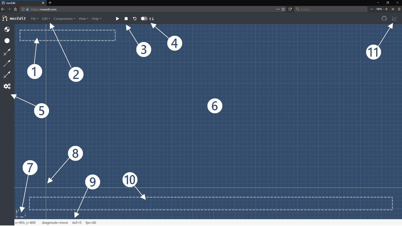
Figure 1 Mechanism Creator after start
Table 1, Mechanism Creator GUI
| # | Name | Function |
|
1 |
message area | Context-sensitive messages and warnings that are used for communication with the user are displayed here. |
| 2 | navigation bar | Contains all functionalities arranged in dropdown menus. |
| 3 | controls | Control the state of the app. |
| 4 | gravity toggle | Switch gravity on or off. |
| 5 | sidebar | Quick access for frequently used components. |
| 6 | editor | Workspace for modeling mechanisms. |
| 7 | coordinate system indicator | Shows the currently used coordinate system. |
| 8 | origin | Origin 0 |
| 9 | status bar | Shows information about the current state and mode of the editor. |
| 10 | input elements | If the model has actuators, their controls are shown here. |
| 11 | chart sidebar | If the model has charts with a property "canvas":Id they will be rendered on canvas elements in this sidebar. |
2) Modeling
To create a valid link in Mechanism Creator, first define two nodes and then connect them with a constraint. Several constraints can be attached to one Node, but constraints always have exactly two nodes. Keep that in mind when you expand your model as you like by adding more nodes and constraints.
3) Load Example
Mechanism Creator provides a number of different examples. Those can be loaded via the navigation bar 2 under File > Load Example and will replace the current model.
4) Import/Export Model
To save a created model locally on your hard drive, select File > Export Model as JSON from the navigation bar at 2. This will open a download dialog where you can select the storage location. You can also export your model as an HTML file in the same way. A microapp is then generated which works as a viewer and which is independent of Mechanism Creator .
To import a model from a JSON file on your hard drive into Mechanism Creator , select the entry File > Import Model from JSON from the navigation bar 2. A window will be opened where you can navigate to the location of your model and select it. Alternatively, you can simply drag and drop the JSON file onto the drawing area. Note that when you import models, your current model will be replaced.
5) Nodes

Figure 2 sidebar
To create a node, click with the left mouse button on the symbol of the desired node-type in the sidebar 5. In the message area 1 you will be asked to click with the left mouse button on any place in the editor to create a node there. Please note that it is not possible to create two nodes on top of each other. If you want to cancel the action without creating a node, this can be done with the ESC key or by clicking on the navigation bar 2 or Sidebar 5. If you want to create several nodes of the same type one after another without having to click the symbol in the sidebar again and again, you can hold down the shift key the first time you click on the symbol. This way the selected function remains active after placing a node, so that the next one can be placed immediately. The function for creating nodes can also be called via the navigation bar 2 under the tab Components > Nodes > Basenode/Node , although you won't be able to make use of chaining from here with the shift key
In the same way, you can add forces for defined nodes Components > Loads > Force as well as fixed and floating bearing symbols Components > Shapes > Fixed Node / Floating Node .
6) Constraints
If there are at least two nodes in the model, they can be linked with a constraint. To do this, left-click on the corresponding arrow symbol in the sidebar 5 to select the constraint type of your choice. In the message area 1 the instruction appears to click first on the start node and then on the end node in the editor window 6 to create the constraint. This component type can also be chain-created by holding the shift when you initially click the symbol. You can then add constraints between nodes until the function is terminated with ESC or by clicking on the navigation bar 2 or Sidebar 5. Alternatively, a call (without chaining) is also possible via the navigation bar 2 and the tab Components > Constraints > Free/Tran/Rot .
Similar to a constraint, you can also define spring elements between two nodes. These can be found in the navigation bar 2 under Components > Loads > Spring .
7) Context Menu
The easiest way to edit components is from the context menu. To access it, click with the left mouse button on the component, that you want to edit, in the editor 6.
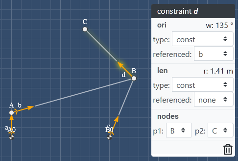
Figure 3 - context menu
A dynamic context menu opens at the cursor position (see 3). The yellow shading of the selected component as well as the the type and ID in the context menus status bar show you what component it currently represents. Due to their many parameters, constraints have the most extensive context menu.
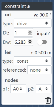
Figure 4 - drive context menu
You can always at least set the type of the degrees of freedom "ori" and "len" as well as the start and end node. If the user changes the type, the context menu is rebuilt with adapted options. The type free is not controlled and therefore has no options. For degrees of freedom of type const (see Figure 2 ) a reference can be specified. The entry none stands for no reference. The type drive always has at least the fields Dt and Dw (or Dr for len instead of ori ). In addition, it is possible to convert the defined drive into a static actuator by toggling the option input? . This creates a slider (see Figure 4] in the input elements area 10, which can be used to manually control the drive.

Figure 5 - slider for actuator
his slider has a button at each end. When you click on one of these buttons, the drive automatically moves through its workspace in the direction indicated on the button. The drive either stops by itself at the end or you can manually stop it by clicking on the same button from which it was started.
All changes in context menus for constraints are only applied once the menu is closed. This is done by clicking in an empty area of the editor 6.
For context menus of other components (nodes and loads), changes are applied immediately to the model and not only when closing it. This is because the context menu does not have to be dynamically rebuilt after changes have been made.
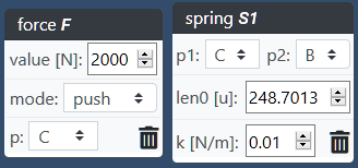
Figure 6 - context menu of loads
All context menus also provide a smart way to delete the associated component. This function is listed by clicking on the trash can symbol . The function is considered smart because it checks whether there are dependencies to other components in the model and whether a deletion of the component would result in an invalid model before actually deleting anything. If this is the case, the user is informed in the message area 1 of the editor and the component is not deleted. If you want to delete components regardless of dependencies, the deletion must be initiated via the navigation bar 2 and the tab Edit > Purge Element. This will delete the component AND everything associated!
Constraints have lots of other optional parameters but since the context menu is intended to be minimalist ic with the user experience kept in mind, these can and should be edited with the help of the integrated JSON-editor.
8) Dragging
Models with a total degree of freedom > 0 can be posed by dragging a node with the mouse pointer. Please consider which drag mode ( drag mode in the status bar) is activated. If you drag a node in drag mode=move mode, the model will move geometrically and kinematically compatible with regard to the defined constraints (the model will be posed). You can switch to the mode to drag mode=edit in the navigation bar 2 Edit > Edit mode or by pressing the key I . By doing that the model will be reset. If you now pull on a node, only this node moves and the model stands still, i.e. the geometry changes. If the mode is changed back again, the new coordinates of the node are set as their standard, thus changing the model.
9) JSON-Editor
Not all model parameters can be edited via the GUI. An integrated JSON-editor is therefore available to add additional options. It can be opened from the navigation bar 2 under Edit > JSON-Editor or by pressing the E key on your keyboard.
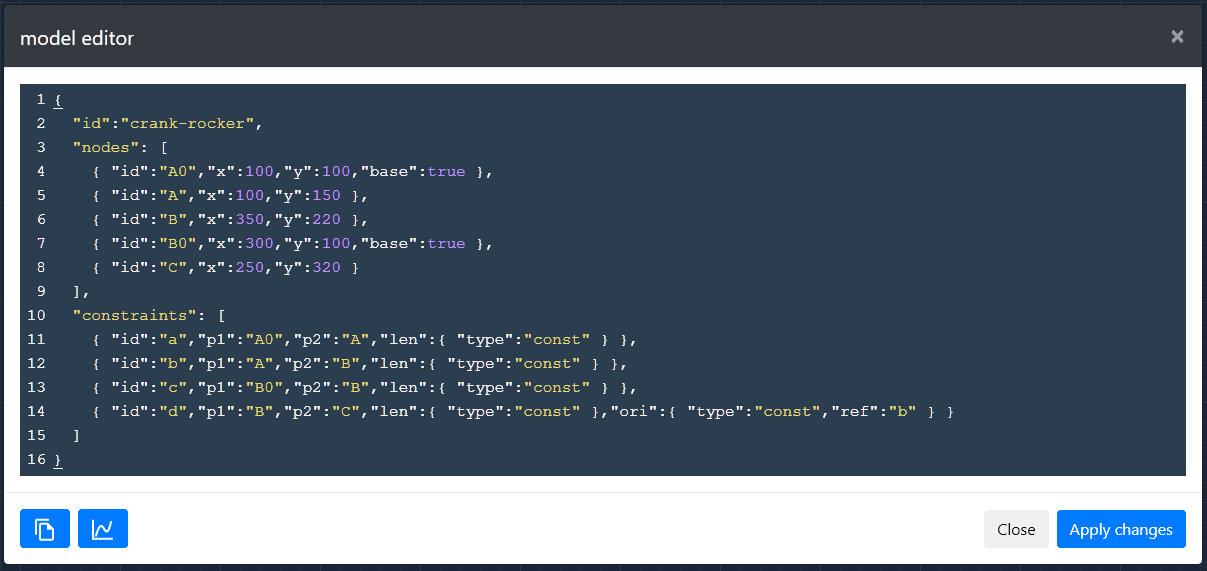
Figure 7 - JSON-editor
Here you can edit the JSON representation of the model. Click the Apply changes button to check the validity of your JSON code, accept changes and reinitialize the model. The editor can then be closed with a click on Close , on x or by pressing the ESC key.
The JSON-editor also contains a button to copy the model to the clipboard and a button to copy a snippet for a chart-view to the clipboard to make it easier to define this component-type.
It is also possible to drag and drop existing models, which are saved locally as JSON files, into the JSON-editor instead of the canvas. By doing so, the content of the JSON-editor will be fully replaced.
View
You can change some view setting for Mechanism Creator from the entry View in the navigation bar 2. You can hide or display Nodes and Constraints from Linkage entry in View > Toggle Graphics or do the same to their labels under Labels .
By clicking on View > Darkmode the editor theme can be switched between light and dark.
The option View > Reset Editor-View restores the position of the origin in case you lost it while panning the view. Panning is possible in the editor window by moving the mouse with pressed middle mouse button or holding down ctrl and left mouse button.
Keyboard Shortcuts
There are some keyboard shortcuts available in Mechanism Creator . These can be displayed from the navigation bar 2 under Help > Keyboard Shortcuts . An overview of currently available keyboard shortcuts is shown in Figure 8
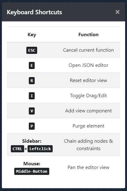
Figure 7 - keyboard shortcuts
Analysis and Simulation
Analysis
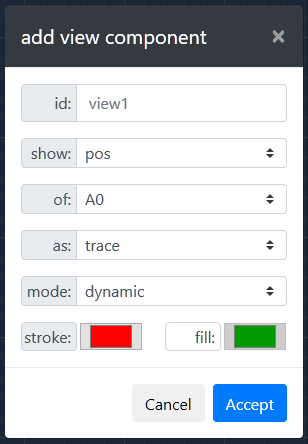
Figure 8 - view modal
Analyses are available in Mechanism Creator through view-components. To create a view, it can either be defined from the JSON-editor according to the mec2-API or added from the entry in the navigation bar ❷ Components > Views . The latter opens a window in which the desired view-component can be semantically defined. After entering an id , the user can first choose what ( show ) to analyze. Then the user chooses the component the analysis should be shown of ( of ) before setting as ( as ) what type it should be displayed. In some cases further parameters can be changed afterwards.
The example in Figure 8creates a trajectory ('Show Position As Trace') of the node with the id A0 . The path is created dynamically during simulation ( "mode": "dynamic" ). The line color is red and the area is not filled because the fill button is transparent and therefore inactive. If the enclosed area should be filled, the fill option can be activated by clicking on the transparent label. This label will then also appear gray. At the same time the color selection for fill becomes active and can be opened.
Since not all analysis values which are available under show can be displayed as all types, only the compatible options ( info , trace , vector ) are displayed to the user.
Simulation
![]()
Figure 9 - Simulation
Models are simulated either by dragging a node into dragmode=move or by using the controls 3. The latter (see Figure 9) has three buttons to control the state of the app, as well as a toggle to switch gravity for the model on or off (displayed in 4). The control buttons are Run (Play-/Pause symbol), Stop (Stop symbol) and Reset (open circle with arrowhead). If the user clicks on the Run button, the model is activated.
If drives (without sliders) are defined, they start to run. With gravitation switched on, the model moves according to its degrees of freedom and the simulated laws of physics, i.e. it strives for a state of equilibrium. If neither drives are defined nor gravity is switched on, nothing happens and the model immediately becomes inactive again.
While the model is in motion, the Run button shows a pause symbol. If you click on the button again, the model can be frozen in its current position while maintaining all kinematic values. Click the Run button again to continue the movement.
A click on the Stop button freezes the moving model in its current pose and sets the velocities and accelerations of all nodes in the model back to 0.
With a click on the Reset button the coordinates of all nodes are reset to their initial values in order to display the model in its initial pose. Any drives and sliders are also reset.
Related
- 2D CAD Static's Modeler and Loads Calculator
- Simple 2D Cad Sketcher
- Simplified Statics 2D modeler and structural reaction loads calculator
- Spur Gear and Gear Assemble Builder
- Electronic Circuit Modeler, Builder and Simulator
- AISC Steel structural Shapes Property Viewer
- Fluid Dynamic Simulator and Stress Reliever
- Truss Calculator Builder And Solver Application
- Stress-Strain Calculator and Plotted Curve Approximation using Ramberg-Osgood Equation
- Visual Math Editor LaTeX, MathML, AsciiMath codes , mhchem and html - Multi Language Support
- Engineering Kinematics
- Theory of Mechanisms and Machines
- Modified Gruebler's Equation for Kinematics Calculator
- Theoretical Mechanics, Kinematics, Dynamics and Static's
- Mechanisms in Modern Engineering Design
- Designing Precision Machines
- Ingenious Mechanisms Volume I for Designers and Inventors
- Ingenious Mechanisms Volume II for Designers and Inventors
- Ingenious Mechanisms Volume III for Designers and Inventors
- Ingenious Mechanisms Volume IV for Designers and Inventors
- Toggle Mechanism Center Locking Design Formula and Calculator
Link to this Webpage:
© Copyright 2000 -
2024, by Engineers Edge, LLC
www.engineersedge.com
All rights reserved
Disclaimer |
Feedback
Advertising
| Contact