Online Static's 2D Modeler and Structural Loads Calculator
Beam Deflection Equations Stress Formula and Calculators
Online 2D Static's Modeler and Structural Capabilities:
- Use mouse/pointer to create and modify 2D Static's model by means of nodes and spans between them.
- Enter a load, modify and remove. A continuous load is entered within each span.
- Enter and remove most common supports (restraints).
- Enter and remove hinges.
- Create sections and assign them to the bars.
- Solve the structure for reactions, internal diagrams and deflected shape.
- Structure can be saved and open. The data are stored locally within your browser.
- Both metric SI and Imperial Units are supported.
Related:
Simplified 2D CAD Static's Modeler and Calculator
Definitions:
kip = USA Customary unit of force = 1,000 pounds-force.
For example, 1 kip = 1,000 pounds-force, .5 kip = 500 pounds-force and .15 kip = 150 pounds-force.
Open: 2D Static's Modeler and Loads Calculator
(Opens a pop-up Window) Premium Membership Required!
See Demonstration Video - 2D Static's Modeler and Loads Calculator Demonstration Video
Scale, Toolbars and Paper Size:
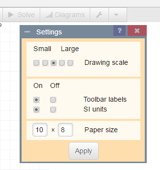
You may want to start by clicking the Settings to switch to imperial units (if you are not familiar with the metric system). Note that you can drag any dialog around by its handle and there is a contextual help available if you click the blue icon with a question mark.
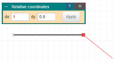
Create spans and nodes:
The bars start and end at nodes. Nodes are by-products of creating the structure. Your supports or hinges can be placed only at nodes. A load can be placed anywhere.
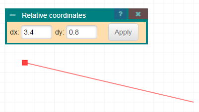
You will likely start the structure by creating bars (spans). You use the pointer to define the beam's start and then move thru the network of grid lines to enter the bar's end.
The bottom grayed dashed line bellow the beam shows where the bottom of the beam is. It is only a matter of convention, which is useful when reading shear force diagrams later. You can change the bottom surface for vertical bars by drawing them from the other ends.
If bars cross each other then they do not interact unless there is a junction or end node that can be connected.
If you are finished placing line bars or need to start at another place, either
- Press ESC key or
- close the Relative coordinates dialog or
- press Abort icon from the toolbar menu.
You can modify created geometry by
- Use the "Select" command
- Select the bars and
- dragging across node(s).
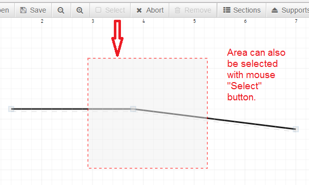
Note: the bars can be selected also by clicking on them.
Drag the node to change the geometry. Note that the functionality is limited and you will likely loose forces (loading) if already applied there.
Finally, press ESC or Abort icon to unselect the beams.
Creating supports and hinges
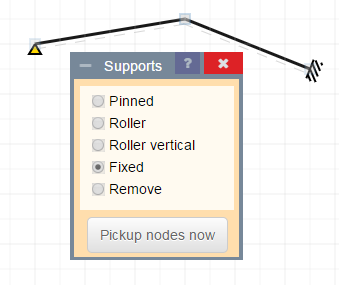
Let's assume that both ends are to be fixed and the middle node is to be loose, i.e. designed as a hinge. First, let you call the Supports icon from the menu, select Fixed support (as required by design) and press Run it button to enter the chosen support type at nodes which you point further.
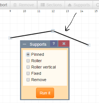
Escape the Supports dialog by selecting the "X" at top right of the dialog box.
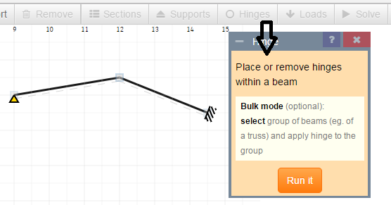
If the dialogs are closed, press Hinges button. Entering a hinge is an analogy to entering a support. But instead of pointing a node you have to point a beam and watch whether the hinge(s) are placed at the required end. If not, point the same beam again until the hinges are placed to your satisfaction. Note: in some cases (structure with braces) you may want to apply hinges to more braces at once rather than pointing brace after brace. That is a case when the bulk mode is handy: apply the function to a selected set of bars or braces.
Applying loading
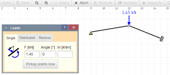
Press Loads button from the toolbar menu. A load can be entered, modified and deleted. A continuous load can be entered only within one span. If you intend to have a continuous load through more spans, you have to repeat the process for each span.
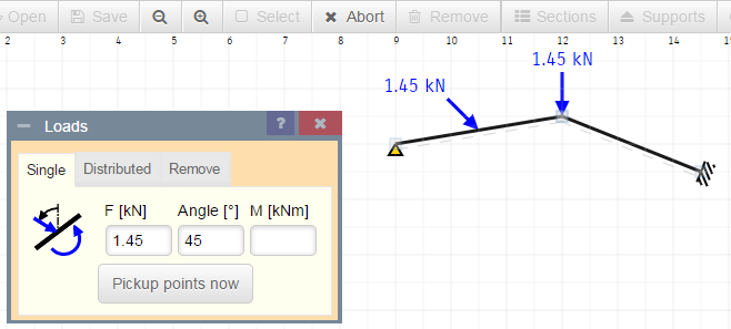
The simplest way to modify or delete a load is to click on the load itself and follow the instructions then.
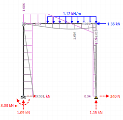
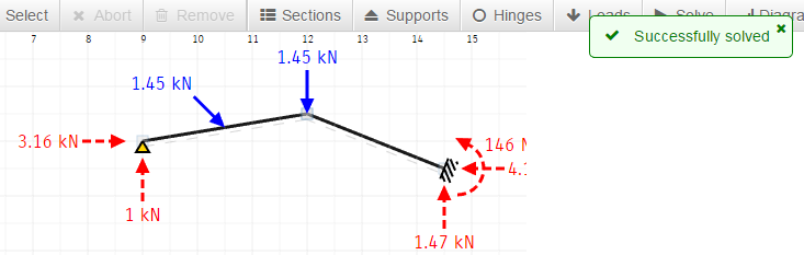
Obtaining reactions and internal forces
If your model is valid, let you press Solve button from the menu. After a while the reactions will appear.
Let you use Diagrams button to control whether and how the internal forces and deflections are drawn.
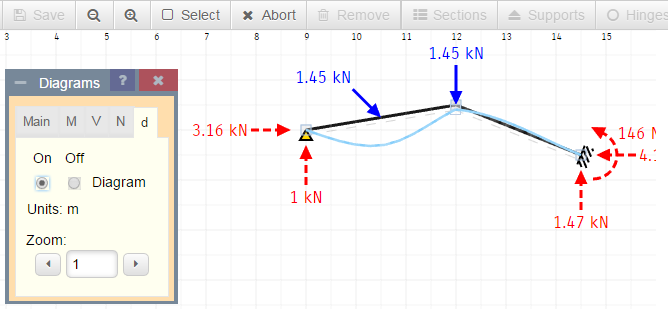
In the above screen shot the deflections are drawn and reactions are disabled. You can also read horizontal and vertical deflection in predetermined points of the structure if you point cursor there (that's usually not possible on touch screens so you have to click instead then). In our above model the deflections would not provide meaningful values as no section was defined.
Load and save
You have two positions for saving your project. The first one is Autosave and you can't save into this position freely since the program maintains it itself. It's handy to use this one to recover in case of an emergency: let you open the Autosave position in such case. It can save you from creating your model again.
The second position can be used to save your project on your request.
Link to this Webpage:
© Copyright 2000 -
2024, by Engineers Edge, LLC
www.engineersedge.com
All rights reserved
Disclaimer |
Feedback
Advertising
| Contact