Related Resources: calculators
Fluid Discharged Distance Coordinates Equations and Calculator
Civil Engineering Application & Design Resources
Fluids Flow Design and Engineering
Fluid Stream From a Container Distance and Coordinates Equations and Calculator
Fluid discharged from an orifice in a tank gets its initial velocity from the conversion of potential energy. After discharge, no additional energy conversion occurs, and all subsequent velocity changes are due to external forces. (See Fig. 1.)
Preview Fluid Stream From a Container Calculator
Figure 1 Coordinates of a Fluid Stream
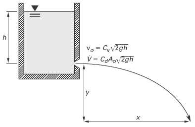
In the absence of air friction (drag), there are no retarding or accelerating forces in the x-direction on the fluid stream. The x-component of velocity is constant. Projectile motion equations can be used to predict the path of the fluid stream.
Eq. 1
Horizontal Discharge at nozzle
vx = vo = Cv ( 2 · g · h )0.5
Eq. 2
Horizontal distance
x = vo · t = vo ( 2 · y / g )0.5 = 2 · Cv ( h · y )0.5
After discharge, the fluid stream is acted upon by a constant gravitational acceleration. The y-component of velocity is zero at discharge but increases linearly with time.
Eq. 3
Vertical discharge velocity
vy = g · t
Eq. 4
Vertical distance
y = g · t2 / 2 = g · x2 / ( 2 vo2 ) = x2 / ( 4 · h · Cv2 )
Eq. 5
Volumetric flow rate
V = Cd · Ao ( 2 · g · h )0.5
Where
vx = Fluid velocity horizontal,
ft/sec, m/s
vy = Fluid velocity vertical, ft/sec, m/s
vo = Acual fluid velocity,
ft/sec, m/s
V =
volumetric flow rate, ft3/sec, m3/s
Ao = area of discharge orifice, ft2, m2
x =
x -coordinate of position, ft, m
y = y -coordinate of position, ft, m
h =
height / depth of head, ft, m
t = time, seconds (s)
g =
gravitational acceleration,
32.2 ft/s2, (9.81 m/s2)
Cv = coefficient of velocity, empirical factor
that accounts for the friction and turbulence at the
orifice, see Table 1
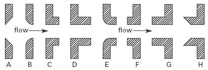
Cd = Approximate Orifice Coefficients for Turbulent Water, see Table 1
Illustration |
Description | Cd |
Cv |
A |
sharp-edged | 0.62 |
0.98 |
B |
round-edged | 0.98 |
0.98 |
C |
short tube* (fluid separates from walls) | 0.61 |
0.61 |
D |
sharp tube (no separation) | 0.82 |
0.82 |
E |
short tube with rounded entrance | 0.97 |
0.98 |
F |
reentrant tube, length less than one-half of pipe diameter | 0.54 |
0.99 |
G r |
eentrant tube, length 2 to 3 pipe diameters | 0.72 |
0.72 |
H |
Borda | 0.51 |
0.98 |
(none) |
smooth, well-tapered nozzle | 0.98 |
0.99 |
*A short tube has a length less than approximately 3 diameters.
Illustrations for Table 1
Source:
Civil Engineering Reference Manual, Fourteenth Edition
Michael R. Lindeburg, PE
Related
- Vertical Tank Draining Time Formulas and Calculator
- Hooghoudt's Drainage Rate Equation and Calculator
- Time to Drain a Conical Tank Equation and Calculator
- Spherical Tank Draining Time Formulas and Calculator
- Horizontal Tank Draining Time Formulas and Calculator
- Orifice Plate Flow Calculations and Design
- Orifice Plate Type Flow Detector Review
- Orifice Submerged in Liquid Discharge Rate Calculator and Equation
- Nozzle Venturi and Orifice Flowmeter Formula and Calculator
- Gas Flow Rate Through Orifice Equations and Calculator per. ISO 5167
- Discharge of Air Through An Orifice Equation and Calculator
- Velocity Escaping Compressed Air Equation and Calculator
- Time to Drain a Conical Tank Equation and Calculator
Link to this Webpage:
© Copyright 2000 -
2024, by Engineers Edge, LLC
www.engineersedge.com
All rights reserved
Disclaimer |
Feedback
Advertising
| Contact