Related Resources: calculators
Gas Flow Rate Through Orifice Equations and Calculator per. ISO 5167
Fluids Flow Design and Engineering
Hydraulic and Pneumatic Design and Engineering
Gas Flow Rate Through Orifice Equations and Calculator per. ISO 5167
ISO 5167 is applicable to orifice plates, nozzles and Venturi tubes when they are inserted in a conduit running full to determine the flow rate of the fluid flowing in the conduit.
Applicable only to pressure differential devices in which the flow remains subsonic throughout the measuring section and where the fluid can be considered as single-phase, but is not applicable to the measurement of pulsating flow. Furthermore, each of these devices can only be used within specified limits of pipe size and Reynolds number.
The mass flow rate can be determined, since it is related to the differential pressure within the uncertainty limits stated in ISO 5167, using Equation (1):
Eq. 1
qm = C / ( 1 - β4 )0.5 · ε · π/4 · d2 · ( 2 · Δp · ρ1 )0.5
or
qm = C · ε · π/4 · d2 · ( 2 · Δp · ρ1 )0.5 / ( 1 - β4 )0.5
Similarly, the value of the volume flowrate can be calculated using Equation (2):
Eq. 2
qv = qm / ρ
where ρ is the fluid density at the temperature and pressure for which the volume is stated
Eq. 3
β = d / D
Eq. 4
β = d / D
Where:
qm = Orifice Mass flowrate, kg / s
qv = Volume flowrate, m3 / s
C = Coefficient of discharge
ε = Expansibility [expansion] factor
d = Diameter of orifice (or throat) of primary device under working conditions, m
D = Upstream internal pipe diameter (or upstream diameter of a
classical Venturi tube) under working conditions, m
p = Absolute static pressure of the fluid, Pa
ρ = Density of the fluid, kg / m3
β = Diameter ratio
Δp = Differential pressure, Difference between the (static) pressures measured at the wall pressure tappings, one of which is on the upstream side and the other of which is on the downstream side of a primary device (or in the throat for a Venturi nozzle or a Venturi tube), inserted in a straight pipe through which flow occurs, when any difference in height between the upstream and downstream tappings has been taken into account
Note: In ISO 5167 (all parts) the term “differential pressure” is used only if the pressure tappings are in the positions specified for each standard primary device.
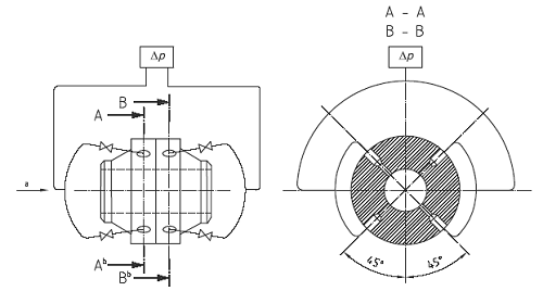
“Triple-T” arrangement
a - flow
b - Section A-A (upstream) alos typical for section B-B (downstream)
Related:
- Pipe Max Flow Rate Maximum recommended flow rates at the given pressure for ANSI schedule 40 pipe.
- Nozzle, Venturi and Orifice Flowmeter Formula and Calculator Flow in a pipeline can be measured by a venturi meter, flow nozzle, or orifice plate.
- Pipe Enlargement and Reduction Head, Heat and Minor Losses Formula
- Liquid Pressure Drop in Pipe and Pipe Fittings Spreadsheet Calculator
- Air Density Equation - Physical properties of air can be represented by the real gas equation, which is the modified version of ideal gas equation.
- Natural Gas Pipe Flow Rate Requirement Formulas and Calculator
- Flow of Air in Pipes Equation and Calculator
- Flow of Compressed Air in Pipes Equation and Calculator
Reference:
International Standard
ISO 5197-1
Measurement of fluid flow by means of
pressure differential devices inserted in
circular cross-section conduits running
full
Link to this Webpage:
© Copyright 2000 -
2024, by Engineers Edge, LLC
www.engineersedge.com
All rights reserved
Disclaimer |
Feedback
Advertising
| Contact