Related Resources: calculators
Nozzle Venturi and Orifice Flowmeter Formula and Calculator
Fluids Engineering and Design Data
Hydraulics and Pneumatics Design and Engineering
Nozzle, Venturi and Orifice Flowmeter Formula and Calculator
Flow in a pipeline can be measured by a venturi meter, flow nozzle, or orifice plate. AmericanSociety of Mechanical Engineers (ASME) Standard MFC-3M describes measurement of fluid flow in pipes using the orifice, nozzle, and venturi; ASME Standard PTC 19.5 specifies their construction.
Preview: Nozzle, Venturi and Orifice Flowmeter Calculator
Assuming an incompressible fluid (liquid or slow-moving gas), uniform velocity profile, frictionless flow, and no gravitational effects, the principle of conservation of mass and energy can be applied to the venturi and nozzle geometries to give the following:
Equation 1
w = ρ · V1 · A1
w = ρ · V2 · A2
w = A2 · [ ( 2 gc · ρ · ( p1 - p2 ) ) / ( 1 - β4 ) ]0.5
Where:
w = mass flow rate, lbm/s
V = velocity of stream, fps
A = flow area, ft2 = π r2 = area of circle
gc = gravitational constant = 32.174 lbm·ft/lbf·s2
ρ = density of fluid, lbm/ft3
p1 = absolute pressure, lbf /ft2
p2 = gauge pressure, lbf /ft2
β = ratio of diameters D2/D1 for venturi and sharp-edge orifice and d /
D for flow nozzle,
D = pipe diameter
d = throat
diameter
Note: Subscript 1 refers to entering conditions; subscript 2 refers to throat conditions.
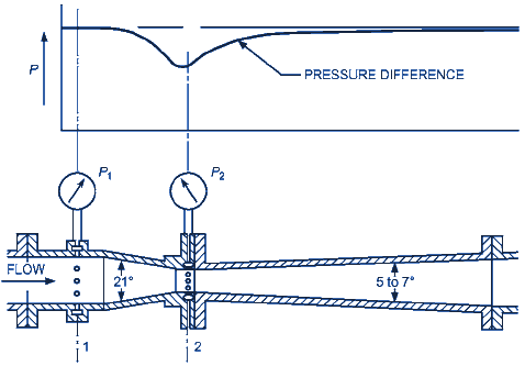
Figure 1 Herschel-Type Venturi Meter - Typical
Because flow through the meter is not frictionless, a correction factor C is defined to account for friction losses. If the fluid is at a high temperature, an additional correction factor Fa should be included to account for thermal expansion of the primary element. Because this amounts to less than 1% at 500°F, it can usually be omitted. Equation (1) then becomes
Equation 2
w = C · A2 · [ ( 2 gc · ρ · ( p1 - p2 ) ) / ( 1 - β4 ) ]0.5
where C is the friction loss correction factor.
The factor C is a function of geometry and Reynolds number. Values of C are given in ASME Standard PTC 19.5. The jet passing through an orifice plate contracts to a minimum area at the vena contracta located a short distance downstream from the orifice plate.
The contraction coefficient, friction loss coefficient C, and approach factor 1 / ( 1 - β4 ) ]0.5can be combined into a single constant K, which is a function of geometry and Reynolds number. The orifice flow rate equations then become
Equation 3
Q = K · A2 · [ ( 2 gc · ( p1 - p2 ) ) / ( ρ ) ]0.5
Where:
Q = discharge flow rate, cfs
A = orifice area, ft2
p1 - p2 = pressure drop as obtained by pressure taps, lbf /ft2
Values of K are shown in ASME Standard PTC 19.5.
Valves, bends, and fittings upstream from the flowmeter can cause errors. Long, straight pipes should be installed upstream and downstream from flow devices to ensure fully developed flow for proper measurement. ASHRAE Standard 41.8 specifies upstream and downstream pipe lengths for measuring flow of liquids with an orifice plate. ASME Standard PTC 19.5 gives piping requirements between various fittings and valves and the venturi, nozzle, and orifice. If these conditions cannot be met, flow conditioners or straightening vanes can be used (ASME Standards PTC 19.5, MFC-10M; Mattingly 1984; Miller 1983).
Compressibility effects must be considered for gas flow if pressure drop across the measuring device is more than a few percent of the initial pressure.
Nozzles are sometimes arranged in parallel pipes from a common manifold; thus, the capacity of the testing equipment can be changed by shutting off the flow through one or more nozzles. An apparatus designed for testing airflow and capacity of air conditioning equipment is described by Wile (1947), who also presents pertinent information on nozzle discharge coefficients, Reynolds numbers, and resistance of perforated plates. Some laboratories refer to this apparatus as a code tester.
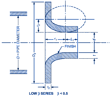
Figure 2 - Long Radius Nozzle From ASME PTC 19.5 - Reprinted with permission
Where (Fig. 2):
r1 = d
r2 = 2/3 d
L1 = 0.6 d
1/8 in ≤ t2 in ≤ 0.15 D
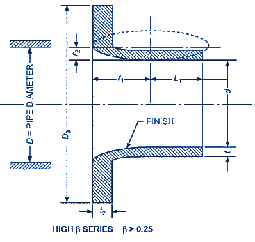
Figure 3 - Long Radius Nozzle From ASME PTC 19.5 - Reprinted with permission
Where (Fig. 3):
r1 = 1/2 d
r2 = 1/2 ( D - d )
L1 ≤ 0.6d or L1 ≤ 1/3 D
2t ≤ D - ( d + 1/8 in.)
1/8 in ≤ t2 in ≤ 0.15 D
Related:
- Extended Bernoulli Concepts and Equations
- Energy Conversions in Fluid Systems Bernoullis Equation
- Simplified Bernoulli Equation - Fluid Flow Hydraulic and Pneumatic
- Pitot Tube Type Flow Detector Review
References:
ASME American Society of Mechanical Engineers PTC 19.5
Link to this Webpage:
© Copyright 2000 -
2024, by Engineers Edge, LLC
www.engineersedge.com
All rights reserved
Disclaimer |
Feedback
Advertising
| Contact