Dowel Pin Installation Design Tolerance Table Chart
Hardware ANSI Menu
Mechanical Tolerance Standards Charts
Dowel Pin Size Chart Machined ASME ANSI
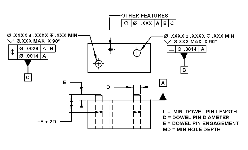
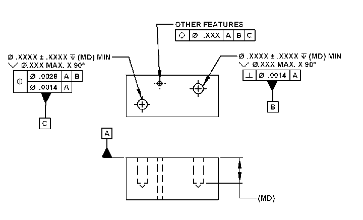
Design for press and slip fit of dowel pins used for alignment of mating parts utilizing GD&T tolerancing methods.
Review your design to determine if you have similar application requirements. Should these design guideline be inadequate, reference the charts given within the Hole - Shaft tolerance pages.
General- Typical material is 6061-T651, per QQ-A-250/11 or similar aluminum alloy for the base mating components.
- Dowel Pin - are stainless steel 304, 306, 18-8 etc .. or similar.
- Application - These fits are for location or alignment applications between two components. Some shear load is acceptable, designer should determine acceptable stress limits for their particular application.
These fits are not line-to-line . Fixed fastener calculations will show minimal interference between dowel pins and slip fit holes. Dowel pins should be installed into press fit holes after finishing processes and not removed there after. After the mating components are assembled the first time, one should note assembly orientation for repeat assembly of mating dowel pins. It is optimal to design for one configuration assembly (fool - proof).
See bottom of page for application illustrations.
| Dowel Pin |
Press Fit Hole |
Slip Fit Hole |
Hole Depth "MD" MIN. |
Pin Engagement "E" |
.031 |
Dia .0305 +/-.0005 V Dia .040 MAX. X 90° |
Dia .0320 +/-.0005 V Dia .040 MAX. X 90° |
.055 +/-.010 |
.025 +/-.010 |
.062 |
Dia .0620 +/-.0005 V Dia .080 MAX. X 90° |
Dia .0635 +/-.0005 V Dia .080 MAX. X 90° |
.070 +/-.010 |
.040 +/-.010 |
.094 |
Dia .0935 +/-.0005 V Dia .120 MAX. X 90° |
Dia .0955 +/-.0005 V Dia .120 MAX. X 90° |
.095 +/-.010 |
.060 +/-.015 |
.125 |
Dia .1245 +/-.0005 V Dia .160 MAX. X 90° |
Dia .1265 +/-.0005 V Dia .160 MAX. X 90° |
.110 +/-.010 |
.075 +/-.015 |
.187 |
Dia .1870 +/-.0005 V Dia .240 MAX. X 90° |
Dia .1895 +/-.0005 V Dia .240 MAX. X 90° |
.145 +/-.010 |
.110 +/-.015 |
.250 |
Dia .2495 +/-.0005 V Dia .315 MAX. X 90° |
Dia .2520 +/-.0005 V Dia .315 MAX. X 90° |
.175 +/-.010 |
.140 +/-.015 |
- These illustrations are toleranced per ASME Y14.5M - 1994 and ASME Y14.5-2009
- Units are in Inches
Dowel Pin Installation Design
Click Images for Larger Images (Pop-up)
Slip Fit Hole Design
Related:
-
American National Standard Unhardened Ground Dowel Pins Chart per. ANSI ASME B18.8.2
- Dowel Pin Slip and Press Fit Installation Tolerance Chart
- Dowel Pin Shear Load Stress Equations and Calculator
- ISO Metric Dowel Pins per DIN EN ISO 8734
- Aircraft Stud, Lock Ring, Dowel Pin, Bolt, Nut Reference Guide Table #6
- Design for Dowel Pin Press Fit
- Bolt or Pin In Single Shear Equation and Calculator
- Bolt Single and Double Shear and Tension Stress Analysis Calculator per AISC 9th Edition
- Bolt or Pin In Double Shear Equation and Calculator
Link to this Webpage:
© Copyright 2000 -
2024, by Engineers Edge, LLC
www.engineersedge.com
All rights reserved
Disclaimer |
Feedback
Advertising
| Contact