Related Resources: hardware
Machine Dowel Pins Chart ANSI ASME
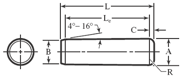
American National Standard Hardened Ground Machine Dowel Pins Chart per. ANSI ASME B18.8.2
ANSI ground machine dowel pins (hardened) are furnished in two diameter series: Standard Series having basic diameters 0.0002 inch over the nominal diameter, intended for initial installations; and Oversize Series having basic diameters 0.001 inch over the nominal diameter, intended for replacement use.
All dimension are in inches
Nominal Size
Nominal Pin Diameter |
Pin Diameter, A |
Point Diameter, B |
Crown Height, C |
Crown Radius, R |
||||||
Standard Series Pins |
Oversize Series Pins |
|||||||||
Basic |
Max |
Min |
Basic |
Max |
Min |
Max |
Min |
Max |
Min |
|
1⁄16
0.0625 |
0.0627 |
0.0628 |
0.0626 |
0.0635 |
0.0636 |
0.0634 |
0.058 |
0.048 |
0.020 |
0.008 |
5⁄64
0.0781 |
0.0783 |
0.0784 |
0.0782 |
0.0791 |
0.0792 |
0.0790 |
0.074 |
0.064 |
0.026 |
0.010 |
3⁄32
0.0938 |
0.0940 |
0.0941 |
0.0939 |
0.0948 |
0.0949 |
0.0947 |
0.089 |
0.079 |
0.031 |
0.012 |
1⁄8
0.1250 |
0.1252 |
0.1253 |
0.1251 |
0.1260 |
0.1261 |
0.1259 |
0.120 |
0.110 |
0.041 |
0.016 |
0.1564 |
0.1565 |
0.1563 |
0.1572 |
0.1573 |
0.1571 |
0.150 |
0.140 |
0.052 |
0.020 |
|
3⁄16
0.1875 |
0.1877 |
0.1878 |
0.1876 |
0.1885 |
0.1886 |
0.1884 |
0.180 |
0.170 |
0.062 |
0.023 |
1⁄4
0.2500 |
0.2502 |
0.2503 |
0.2501 |
0.2510 |
0.2511 |
0.2509 |
0.240 |
0.230 |
0.083 |
0.031 |
5⁄16
0.3125 |
0.3127 |
0.3128 |
0.3126 |
0.3135 |
0.3136 |
0.3134 |
0.302 |
0.290 |
0.104 |
0.039 |
3⁄8
0.3750 |
0.3752 |
0.3753 |
0.3751 |
0.3760 |
0.3761 |
0.3759 |
0.365 |
0.350 |
0.125 |
0.047 |
7⁄16
0.4375 |
0.4377 |
0.4378 |
0.4376 |
0.4385 |
0.4386 |
0.4384 |
0.424 |
0.409 |
0.146 |
0.055 |
1⁄2
0.5000 |
0.5002 |
0.5003 |
0.5001 |
0.5010 |
0.5011 |
0.5009 |
0.486 |
0.471 |
0.167 |
0.063 |
5⁄8
0.6250 |
0.6252 |
0.6253 |
0.6251 |
0.6260 |
0.6261 |
0.6259 |
0.611 |
0.595 |
0.208 |
0.078 |
3⁄4
0.7500 |
0.7502 |
0.7503 |
0.7501 |
0.7510 |
0.7511 |
0.7509 |
0.735 |
0.715 |
0.250 |
0.094 |
7⁄8
0.8750 |
0.8752 |
0.8753 |
0.8751 |
0.8760 |
0.8761 |
0.8759 |
0.860 |
0.840 |
0.293 |
0.109 |
1
1.0000 |
1.0002 |
1.0003 |
1.0001 |
1.0010 |
1.0011 |
1.0009 |
0.980 |
0.960 |
0.333 |
0.125 |
Nominal Size
Nominal Pin Diameter |
Single Shear Load, for Carbon or Alloy Steel, Calculated, lb |
Suggested Hole Diameter |
|
Max |
Min |
||
1⁄16
0.0625 |
400 |
0.0625 |
0.0620 |
5⁄64
0.0781 |
620 |
0.0781 |
0.0776 |
3⁄32
0.0938 |
900 |
0.0937 |
0.0932 |
1⁄8
0.1250 |
1,600 |
0.1250 |
0.1245 |
2,500 |
0.1562 |
0.1557 |
|
3⁄16
0.1875 |
3,600 |
0.1875 |
0.1870 |
1⁄4
0.2500 |
6,400 |
0.2500 |
0.2495 |
5⁄16
0.3125 |
10,000 |
0.3125 |
0.3120 |
3⁄8
0.3750 |
14,350 |
0.3750 |
0.3745 |
7⁄16
0.4375 |
19,550 |
0.4375 |
0.4370 |
1⁄2
0.5000 |
25,500 |
0.5000 |
0.4995 |
5⁄8
0.6250 |
39,900 |
0.6250 |
0.6245 |
3⁄4
0.7500 |
57,000 |
0.7500 |
0.7495 |
7⁄8
0.8750 |
78,000 |
0.8750 |
0.8745 |
1
1.0000 |
102,000 |
1.0000 |
0.9995 |
All dimensions are in inches.
Click on image to enlarge

a Nonpreferred sizes, not recommended for use in new designs
b Lengths increase in 1/16-inch steps up to 3/8 inch, in 1/8-inch steps from 3/8 inch to 1 inch, in 1/4-inch steps from 1 inch to 2 1/2 inches, and in 1/2-inch steps above 2 1/2 inches. Tolerance on length is ± 0.010 inch.
c These press hole sizes have been commonly used for press fitting Standard Series machine dowel pins into materials such as mild steels and cast iron. In other materials, such as aluminum or zinc die castings, hole size limits are usually decreased by 0.0005 inch to increase the interfearance of the press fit.
Related:
- Dowel Pin Slip and Press Fit Installation Tolerance Chart
- Dowel Pin Shear Load Stress Equations and Calculator
- ISO Metric Dowel Pins per DIN EN ISO 8734
- Aircraft Stud, Lock Ring, Dowel Pin, Bolt, Nut Reference Guide Table #6
- Design for Dowel Pin Press Fit
- Bolt or Pin In Single Shear Equation and Calculator
- Bolt Single and Double Shear and Tension Stress Analysis Calculator per AISC 9th Edition
- Bolt or Pin In Double Shear Equation and Calculator
Reference:
American National Standard Hardened Ground Machine Dowel Pins ANSI/ASME B18.8.2
Link to this Webpage:
© Copyright 2000 -
2024, by Engineers Edge, LLC
www.engineersedge.com
All rights reserved
Disclaimer |
Feedback
Advertising
| Contact