Related Resources: hardware
Groove Design for Metric ISO Size O-Rings per. ISO 3601-2
Fluids, Piping and Hydraulic Design Data
Groove Design for Metric ISO Size O-Rings per. ISO 3601-2
An initial compression (squeeze) of the O-Ring in the groove is essential to ensure its function as a primary or secondary sealing element. It serves to:
- Achieve the initial sealing capability
- Bridge production tolerances
- Assure defined frictional forces
- Compensate for the compression set
- Compensate for wear
Depending on the application, the following values apply
for the initial squeeze as a proportion of the cross section
(d2):
Dynamic applications: 6 to 20%
Static applications: 15 to 30%
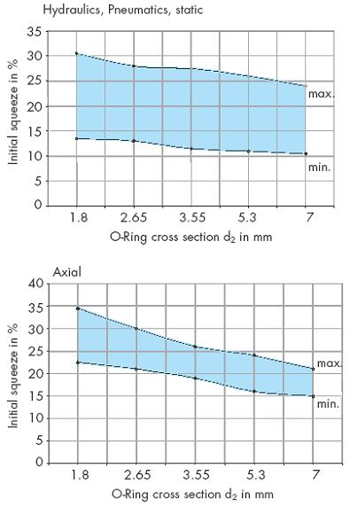
The design of the grooves can be based on the guide values for the initial squeeze shown in the diagrams in Figure 1 and 2. These take into account the relationship between loads and cross sections according to ISO 3601-2 (version 1987).
Figure 1, Permissible range of initial squeeze as a
function of cross section, radial dynamic

Figure 2, Permissible range of Initial squeeze as a
function of cross section, radial static and axial
Shaft and bores
Figure 3, Lead-in chamfers for bores, tubes
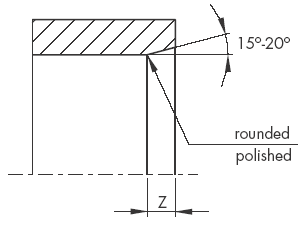
Figure 4 Lead-in chamfers for shafts, rods
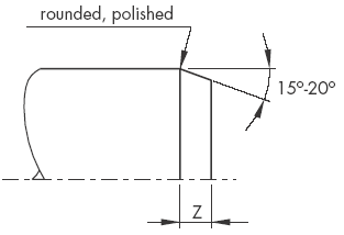
Table 1, Lead Lead-in Chamfers
Lead-in chamfers length Z min. |
O-Ring cross section d2 |
|
15° |
20° |
|
2.5 |
2.0 |
up to 1.78 1.80 |
3.5 |
2.5 |
up to 2.62 2.65 |
4.5 |
3.5 |
up to 3.53 3.55 |
5.0 |
4.0 |
up to 5.33 5.30 |
6.0 |
4.5 |
up to 7.00 |
The surface roughness of a lead-in chamfer is:
RZ ≤ 6.3 µm
Ra ≤ 0.8 µm
The tolerances given in table XV and the maximum permissible radial clearance S (extrusion gap) given in the table XII must be maintained.
If the clearance is too large, there is a risk of seal extrusion which can result in the destruction of the O-Ring
Figure 5 Radial clearance “S“
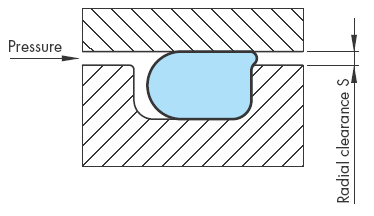
Figure 6, O-Ring installation recommendations
This Chart Calculator Specifies Groove design for o-ring sizes ranging from 0.5 to 12.00 mm per. ISO 3601-2. (Premium Membership required)
Preview: Groove design for o-ring sizes table calculator
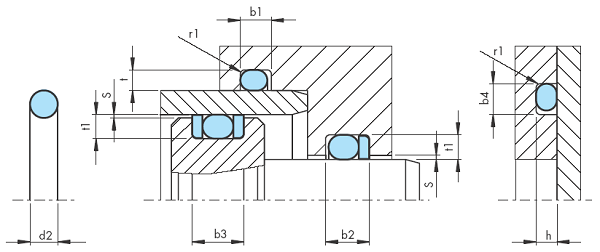
1) When using Back-up Rings the groove is to be widened by the corresponding Back-up Ring thickness (b2: one Back-up Ring, b3: two Back-up Rings).
2) If a Back-up Ring is used the recommended radius r1 should
always be r1= 0.25 ±0.2mm.
Reference:
ISO 3601-2, (Version 1987)
Related:
- Analysis of large-sized O-rings used in pressure chambers
- Mechanical Seal Balance Ratio Formula and Calculator
- Specification for Rubber Gaskets Free Membership Required
- Rubber Molding Design Guidelines and Review
- Poppet Seal Gasket Oring Operating Life and Reliability Equations and Calculator
- O-Ring, Design Considerations General
- O-Ring Installation, Design & Specification Gland (Groove) Sizes Static Cylindrical Applications
- O-Ring Installation, Design & Specification Gland (Groove) Sizes Static Flange Application
- O-Ring Installation Design & Specification For Dynamic / Reciprocating Applications
- O-Ring Installation Compressive Load vs Hardness Chart .070 Diameter ORing
- O-Ring Installation Compressive Load vs Hardness Chart .103 Diameter ORing
- O-Ring Installation Compressive Load vs Hardness Chart .139 Diameter ORing
- O-Ring Installation Compressive Load vs Hardness Chart .210 Diameter ORing
- O-Ring Installation Compressive Load vs Hardness Chart .275 Diameter ORing
Link to this Webpage:
© Copyright 2000 -
2024, by Engineers Edge, LLC
www.engineersedge.com
All rights reserved
Disclaimer |
Feedback
Advertising
| Contact