Related Resources: calculators
Mechanical Seal Balance Ratio Formula and Calculator
Fluid Flow Hydraulic and Pneumatic Engineering and Design Menu
Mechanical Seal Balance Ratio Formula and Calculator
As a means of quantifying the amount, or percent, of balance for a mechanical seal, a ratio can be made between the seal face area above the balance diameter versus the total seal face area. This ratio can also be expressed as the area of the seal face exposed to hydraulic closing force versus the total seal face area.
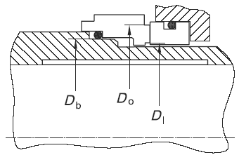
Figure 1, Seal with higher pressure at outer diameter (API-682. Courtesy of American Petroleum Institute.)
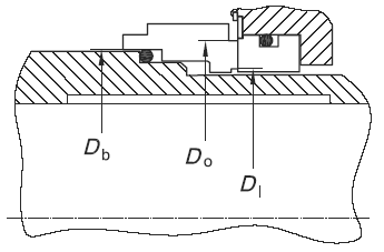
Figure 2, Seal with higher pressure at inner diameter (API-682. Courtesy of American Petroleum Institute.)
Preview: Mechanical Seal Balance Ratio Calculator
In either case, referring to Figure 1 and 2, the mathematical expression for the balance ratio of an inside and outside seal designs are:
For seals pressurized at the outside diameter, the seal balance ratio, B, is defined by the simplified equation:
Eq. 1
B = ( Do2 - Db2 ) / ( Do2 - Di2 )
where:
Do = seal face outside diameter (in, mm);
Di = seal face inside diameter (in, mm);
Db = balance diameter of the seal (in, mm).
For seals pressurized at the inner diameter, the seal balance ratio is defined by the equation:
Eq. 2
B = ( Db2 - Di2 ) / ( Do2 - Di2 )
Where:
Do = seal face outside diameter (in, mm);
Di = seal face inside diameter (in, mm);
Db = balance diameter of the seal (in, mm).
As a general rule of thumb, balanced seal designs use a balance ratio of 0.75 for water and non flashing hydrocarbons. For flashing hydrocarbons, which are fluids with a vapor pressure greater than atmospheric pressure at the service temperature, the balance ratio is typically 0.80 to 0.85. Unbalanced seal designs typically have a ratio of 1.25 to 1.35.
Balance diameter varies with seal design, but for spring pusher seals under outer-diameter pressure, it is normally the diameter of the sliding contact surface of the inner diameter of the dynamic O-ring; for spring pusher seals under inner-diameter pressure, it is normally the diameter of the sliding contact surface of the outer diameter of the dynamic O-ring; for welded metal bellows-type seals, the balance diameter is normally the mean diameter of the bellows, but this can vary with pressure.
Temperature control plays an important role in the success of a mechanical seal. Every seal generates heat at the seal faces. In some cases, heat soak from the fluid pumped should also be controlled. Heat soak is the heat transferred from the pump and pumped fluid to fluid in the seal chamber. For example, if a particular fluid must be maintained at 60 °C (140 °F) to maintain a satisfactory vapour pressure margin and the pump operating temperature is 146 °C (295 °F), heat would be transferred through the pump case into the seal chamber.
Related:
- O-Ring Installation Design and Specification Static Flange Application
- O-Ring Installation Design and Specification Static Cylindrical Installations
- O-Ring Installation Design and Specification For Dynamic Applications
- O-Rings Design Guidelines, Specifications, Materials
- O-Ring Installation Compressive Load vs Hardness Chart .275 Diameter O-Ring
- O-Ring Leak Rate Equation and Calculator
Reference:
- API/ANSI Standard 382 - Pumps Shaft Sealing Systems for Centrifugal and Rotary Pumps
- Rules of Thumb for Mechanical Engineers
J. Edward Pope, Editor
Link to this Webpage:
© Copyright 2000 -
2024, by Engineers Edge, LLC
www.engineersedge.com
All rights reserved
Disclaimer |
Feedback
Advertising
| Contact