Related Resources: calculators
Distance Between Bearings on Shaft Design Formula and Calculator
Bearing Engineering and Knowledge Application Menu
Distance Between Bearings on Shaft Design Formula and Calculator
The shaft which the bearings are installed on are potentially subject to both bending and torsion forces and must be accounted for in the design installation and spacing of bearings. Also, a factor of or margin of safety must be applied. The maximumbearing distance of separation may be calculated as follows
Instead of computing the transverse deflection, the maximum distance between the bearings (in meters) may be computed by the empirical formula to limit the transverse deflection to 0.8mm/m of length
Distance between bearings (Reference 1)
Eq. 1
L = 1500 / ( n + 1500 ) c D( 2/3 )
Values of constant c
| Type of shaft loading | Coefficient c |
Allowable stress |
|
MPa |
kpsi |
||
| Shaft heavily loaded, subjected to shock, or reversed under full load | 0.82 |
17 |
2.5 |
Line shafts and countershafts, |
1.1 |
27 |
4.0 |
| Line shafts or bar with pulleys close to the bearings | 1.56 |
44 |
6.4 |
Alternatively
The shaft-bearing spacing formula is based on the formula for critical speed for a shaft having fully flexible bearings at both ends.
Eq. 2 (Reference 2)
L = [ 3.21 D ) / n ](1/2) ( E / W1 ](1/4)
Where
D = diameter of solid shaft, m (in)
L = Unsupported distance between bearings
n = speed, rpm
E = Modulus of elasticity
W1 = weght in lbs of shaft
Note: The minimum minimum spacing for RIGID bearings should exceed 20 shaft diameters when possible to facilitate alignment
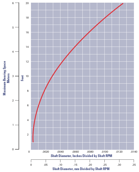
Figure 1 Bearing Spacing Design Graph - Click on Image to enlarge
References
1. Lingaiah, K., and B. R. Narayana Iyengar, Machine Design Data Handbook, Engineering College Cooperative, Bangalore, India, 1962.
2. Aqualoy Propeller Shafting
Related
- Critical Speeds of Rotating Shafts with Single Loads Equations and Calculators
- Critical Speeds of Rotating Shafts with Single Loads, First Critical Speed
- Critical Speed Ball Screw and Lead Screws Formulas and Calculator
- Ball and Roller Bearing Analysis Loading and Selection Formulas and Calculator
- Bearing Life Formula Based on Speed, Load and Hardness, Ball Bearings, Radial
- Force Analysis Four Point Contact Ball Bearings Four point contact ball bearings are capable of resisting radial, thrust, and moment loads, it is ordinarily subjected to a combination of two or more of these loads wherever it is applied.
- Shaft to Shaft Axial Alignment Design Tolerances Tables Design for shaft-to-shaft alignment is the positioning of the rotational centers of two or more shafts so that the shafts are co-axial when the machine is in operation.
- Beam Deflection and Stress Calculator Simply supported on each end
Link to this Webpage:
© Copyright 2000 -
2024, by Engineers Edge, LLC
www.engineersedge.com
All rights reserved
Disclaimer |
Feedback
Advertising
| Contact