Related Resources: hardware
Coiled Spring Pins
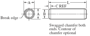
Coiled Spring Pins per ANSI/ASME B18.8.2
Coiled Spring Pins are typically for hinge pin and pivots, for locating and alignment, attaching a gear to a shaft / collar, and for fastening two or more components together.
All units are in inches
Nominal Size or Basic Pin Diameter |
Pin Diameter, A |
Chamfer |
Recommended Hole Size |
|||||||
Standard Duty |
Heavy Duty |
Light Duty |
Dia., B |
Length, C |
Recommended Hole Size |
|||||
Max |
Min |
Max |
Min |
Max |
Min |
Max |
Ref |
Max |
Min |
|
1⁄32 0.031 |
0.035 |
0.033 |
… |
… |
… |
… |
0.029 |
0.024 |
0.032 |
0.031 |
1⁄32 0.039 |
0.044 |
0.041 |
… |
… |
… |
… |
0.037 |
0.024 |
0.040 |
0.039 |
3⁄64 0.047 |
0.052 |
0.049 |
… |
… |
… |
… |
0.045 |
0.024 |
0.048 |
0.046 |
3⁄64 0.052 |
0.057 |
0.054 |
… |
… |
… |
… |
0.050 |
0.024 |
0.053 |
0.051 |
1⁄16 0.062 |
0.072 |
0.067 |
0.070 |
0.066 |
0.073 |
0.067 |
0.059 |
0.028 |
0.065 |
0.061 |
5⁄64 0.078 |
0.088 |
0.083 |
0.086 |
0.082 |
0.089 |
0.083 |
0.075 |
0.032 |
0.081 |
0.077 |
3⁄32 0.094 |
0.105 |
0.099 |
0.103 |
0.098 |
0.106 |
0.099 |
0.091 |
0.038 |
0.097 |
0.093 |
7⁄64 0.109 |
0.120 |
0.114 |
0.118 |
0.113 |
0.121 |
0.114 |
0.106 |
0.038 |
0.112 |
0.108 |
1⁄8 0.125 |
0.138 |
0.131 |
0.136 |
0.130 |
0.139 |
0.131 |
0.121 |
0.044 |
0.129 |
0.124 |
5⁄32 0.156 |
0.171 |
0.163 |
0.168 |
0.161 |
0.172 |
0.163 |
0.152 |
0.048 |
0.160 |
0.155 |
3⁄16 0.188 |
0.205 |
0.196 |
0.202 |
0.194 |
0.207 |
0.196 |
0.182 |
0.055 |
0.192 |
0.185 |
7⁄32 0.219 |
0.238 |
0.228 |
0.235 |
0.226 |
0.240 |
0.228 |
0.214 |
0.065 |
0.224 |
0.217 |
1⁄4 0.250 |
0.271 |
0.260 |
0.268 |
0.258 |
0.273 |
0.260 |
0.243 |
0.065 |
0.256 |
0.247 |
5⁄16 0.312 |
0.337 |
0.324 |
0.334 |
0.322 |
0.339 |
0.324 |
0.304 |
0.080 |
0.319 |
0.308 |
3⁄8 0.375 |
0.403 |
0.388 |
0.400 |
0.386 |
0.405 |
0.388 |
0.366 |
0.095 |
0.383 |
0.370 |
7⁄16 0.438 |
0.469 |
0.452 |
0.466 |
0.450 |
0.471 |
0.452 |
0.427 |
0.095 |
0.446 |
0.431 |
1⁄2 0.500 |
0.535 |
0.516 |
0.532 |
0.514 |
0.537 |
0.516 |
0.488 |
0.110 |
0.510 |
0.493 |
5⁄8 0.625 |
0.661 |
0.642 |
0.658 |
0.640 |
… |
… |
0.613 |
0.125 |
0.635 |
0.618 |
3⁄4 0.750 |
0.787 |
0.768 |
0.784 |
0.766 |
… |
… |
0.738 |
0.150 |
0.760 |
0.743 |
Related:
- Dowel Pin Slip and Press Fit Installation Tolerance Chart
- Dowel Pin Shear Load Stress Equations and Calculator
- ISO Metric Dowel Pins per DIN EN ISO 8734
- Aircraft Stud, Lock Ring, Dowel Pin, Bolt, Nut Reference Guide Table #6
- Design for Dowel Pin Press Fit
- Bolt or Pin In Single Shear Equation and Calculator
- Bolt Single and Double Shear and Tension Stress Analysis Calculator per AISC 9th Edition
- Bolt or Pin In Double Shear Equation and Calculator
Reference:
ANSI/ASME B18.8.2
Link to this Webpage:
© Copyright 2000 -
2024, by Engineers Edge, LLC
www.engineersedge.com
All rights reserved
Disclaimer |
Feedback
Advertising
| Contact