Related Resources: calculators
Torsion Spring Design Formula and Calculator
Spring Design and Engineering Equations and Calculators
Design of Helical Torsion Spring Formula and Calculator
- Mean diameter of a helical torsion
- Spring diameter under deflection
- Stress in torsion springs
- Failure rate of a torsion spring
Mechanical springs are used in machine designs to exert force, provide flexibility, and to store or absorb energy. Springs are manufactured for many different Springs applications such as compression, extension, torsion, power, and constant force. Depending on the application, a spring may be in a static, cyclic or dynamic operating mode. A spring is usually considered to be static if a change in deflection or load occurs only a few times, such as less than 10,000 cycles during the expected life of the spring. A static spring may remain loaded for very long periods of time. The failure modes of interest for static springs include spring relaxation, set and creep.
Figure 1a - Torsion Spring
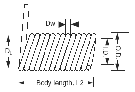
Figure 1b - Torsion Spring
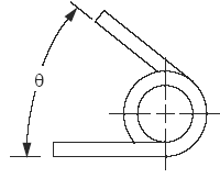
Helical torsion springs are used to apply a torque or store rotational energy, the most common application, the clothes pin. Torsion springs are stressed in bending as shown in Figure 1a and 1b. A torsion spring should always be loaded in a direction that causes its body diameter to decrease because of increased stresses when the spring is loaded in a direction which increases body diameter.
Preview: Design of Helical Torsion Spring Calculator
The mean diameter of a helical torsion spring is equal to:
Eq. 1
DI = ( ID + OD ) / 2
The spring diameter will change with deflection according to the following equation:
Eq. 2
DC = ( DI · Na ) / ( Na + θ )
Where:
DC = Mean diameter after deflection, in., (mm)
DI = Initial mean diameter, in., (mm)
ID = Internal diameter, in., (mm)
OD = Outside diameter, in., (mm)
θ = Angular deflection from free position, revolutions
Na = Number of active coils
Most torsion springs are close-wound, with body length equal to wire diameter multiplied by the number of turns plus one.
Eq. 3
L = Dw · Na + 1
When the spring is deflected in a direction which reduces its coil diameter, body length increases to L2 according to the following equation:
Eq. 4
L2 = Dw · ( Na + 1 + θ )
Where
Dw = Wire diameter, in
L2 = Body length increase to , in, (mm)
Stress in torsion springs is due to bending and for round wire is calculated with the following equation:
Eq. 5
S = ( 3 · EM · Dw · θ ) / ( π · DI · Na )
Where:
S = Bending stress, lbs/in2, (N/mm2)
EM = Modulus of Elasticity, lbs/in2, (N/mm2)
Dw = Wire diameter, in, (mm)
θ = Angular deflection, revolutions
DI = Mean diameter of spring, in, (mm)
Na = Number of active coils
The equation to determine the failure rate of a torsion spring can be written as follows:
Eq. 6
λSP = λSP,B · ( S / Ts )3 · Ccs · CR · CM
From this equation a generalized equation can be developed containing a base failure rate with applicable multiplying factors:
Eq. 7
λSP = λSP,B · CE · CDW · CN · CY · CL · CCS · CDC · CR · CM
where:
λSP = Failure rate of torsion spring, failures/million hours
λSP,B = Base failure rate for torsion spring, 14.3 failures/million hours
CE = Multiplying factor which considers the effect of the material elasticity modulus on the base failure rate
Eq. 8
CE = ( EM / 28.5 x 10⁶ )3
CDW = ( Dw / 0.085 )3
Eq. 9
CDW = Multiplying factor which considers the effect of the wire diameter on the base failure rate
CN = Multiplying factor which considers the effect of the number of active coils on the base failure rate
Eq. 10
CN = ( 14 / Na )3
CY = Multiplying factor which considers the effect of material tensile strength on the base failure rate
Eq. 11
CY = ( 190 x 103 / Ts )3
Ts = Tensile Strength, lbs/in2, (N/mm2)
CL = Multiplying factor which considers the effect of spring deflection on the base failure rate
Eq. 12
CL = ( ( L2 - L ) / 1.07)3
CDC = Multiplying factor which considers the effect of coil diameter on the base failure rate
Eq. 13
CDC = ( 0.58 / DC )3
CCS = Multiplying factor which considers the effect of a corrosive environment on the base failure rate
Eq. 14a
CCS = 0.100 If CR ≤ cycles/min
Eq. 14b
CCS = CR / 300 ) For 30 cycles/min < CR ≤ 300 cycles min,
Eq. 14c
CCS = ( CR / 300 )3 ForCR > 300 cycles/min,
CR = Multiplying factor which considers the effect of a corrosive environment on the base failure rate
Eq. 15
CR = 1.0 unless or greater than 1.0 with user's experience with the spring and the operating environment.
CM = Multiplying factor which considers the effect of the manufacturing process on the base failure rate
Eq. 15
CM = 1.0 a higher value for the multiplying factor is used based on previous experience with the manufacturer.
Reference:
Handbook of of Reliability Predictions Procedure for Mechanical Equipment
Logistics Technology Support
CARDEROCKDIV, NSWC-11
2011
Related
- Torsion Spring Arc Length Formula and Calculator
- Torsion Spring Calculator
- Torsion Applied Spring Stiffness Constant Equations and Calculator
- Coil-Diameter Tolerances of Torsion Springs Specifications
- Morrison's Spring Tables Design Reference Premium Membership Required to view Document/Book
- Typical Modulus of Elasticity of Spring Materials used in Torsion and Tension
- Mass Spring Simulator and Calculator
- Spring Properties and Material
- Springs Made From Rectangular Section Bar Steel Design and Calculations
- Stresses in Helical Springs Produced by Shocks Formulas and Calculator
Link to this Webpage:
© Copyright 2000 -
2024, by Engineers Edge, LLC
www.engineersedge.com
All rights reserved
Disclaimer |
Feedback
Advertising
| Contact