Power Plant Components - Thermodynamics
Thermodynamics Directory | Heat Transfer Directory
Power Plant Components
In order to analyze a complete power plant steam power cycle, it is first necessary to analyze the elements which make up such cycles. (See Figure 26) Although specific designs differ, there are three basic types of element sin power cycles, (1) turbines, (2) pumps and (3) heat exchangers. Associated with each of these three types of elements is a characteristic change in the properties of the working fluid. Previously we have calculated system efficiency by knowing the temperature of the heat source and the heat sink . It is also possible to calculate the efficiencies of each individual component. The efficiency of each type of component can be calculated by comparing the actual work produced by the component to the work that would have been produced by an ideal component operating is entropically between the same inlet and outlet conditions.
A steam turbine is designed to extract energy from the working fluid (steam) and use it to do work in the form of rotating the turbine shaft. The working fluid does work as it expands through the turbine. The shaft work is then converted to electrical energy by the generator. In the application of the first law, general energy equation to a simple turbine under steady flow conditions, it is found that the decrease in the enthalpy of the working fluid Hin -Hout equals the work done by the working fluid in the turbine (Wt).
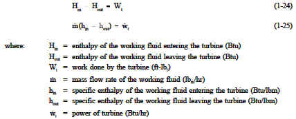
These relationships apply when the kinetic and potential energy changes and the heat losses of the working fluid while in the turbine are negligible. For most practical applications, these are valid assumptions. However, to apply these relationships, one additional definition is necessary. The steady flow performance of a turbine is idealized by assuming that in an ideal case the working fluid does work reversibly by expanding at a constant entropy. This defines the so-called ideal turbine. In an ideal turbine, the entropy of the working fluid entering the turbine Sin equals the entropy of the working fluid leaving the turbine.
![]() in =Sout
in =Sout
![]() in =sout
in =sout
where:
Sin = entropy of the working fluid entering the turbine (Btu/oR)
![]() out = entropy of the working fluid leaving the turbine (Btu/oR)
out = entropy of the working fluid leaving the turbine (Btu/oR)
![]() in = specific entropy of the working fluid entering the turbine (Btu/lbm -oR)
in = specific entropy of the working fluid entering the turbine (Btu/lbm -oR)
![]() out = specific entropy of the working fluid leaving the turbine (Btu/lbm -oR)
out = specific entropy of the working fluid leaving the turbine (Btu/lbm -oR)
The reason for defining an ideal turbine is to provide a basis for analyzing the performance of turbines. An ideal turbine performs the maximum amount of work theoretically possible.
An actual turbine does less work because of friction losses in the blades, leakage past the blades and, to a lesser extent, mechanical friction. Turbine efficiency η t, sometimes called isentropic turbine efficiency because an ideal turbine is defined as one which operates at constant entropy,
is defined as the ratio of the actual work done by the turbine Wt, actual to the work that would be done by the turbine if it were an ideal turbine Wt,ideal. W![]() t,actual
t,actual
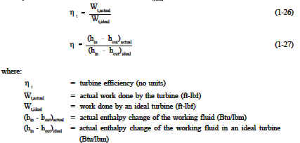
In many cases, the turbine efficiency η t has been determined independently. This permits the actual work done to be calculated directly by multiplying the turbine efficiency η t by the work done by an ideal turbine under the same conditions. For small turbines, the turbine efficiency is generally 60% to 80%; for large turbines, it is generally about 90%.
The actual and idealized performances of a turbine may be compared conveniently using a T-s diagram. Figure 27 shows such a Figure 27 Comparison of Ideal and Actual Turbine Performances comparison. The ideal case is a constant entropy. It is represented by a vertical line on the T-s diagram. The actual turbine involves an increase in entropy. The smaller the increase in entropy, the closer the turbine efficiency η t is to 1.0 or 100%.
A pump is designed to move the working fluid by doing work on it. In the application of the first law general energy equation to a simple pump under steady flow conditions, it is found that the increase in the enthalpy of the working fluid Hout -Hin equals the work done by the pump, Wp, on the working fluid.
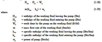
These relationships apply when the kinetic and potential energy changes and the heat losses of the working fluid while in the pump are negligible. For most practical applications, these are valid assumptions. It is also assumed that the working fluid is incompressible. For the ideal case, it can be shown that the work done by the pump Wp is equal to the change in enthalpy across the ideal pump.

The reason for defining an ideal pump is to provide a basis for analyzing the performance of actual pumps. A pump requires more work because of unavoidable losses due to friction and fluid turbulence. The work done by a pump Wp is equal to the change in enthalpy across the actual pump.
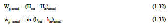
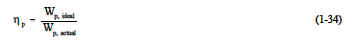
Pump efficiency, η p, is defined as the ratio of the work required by the pump if it were an ideal p, ideal to the actual work required by the pump wp, actual. W![]() p, ideal
p, ideal
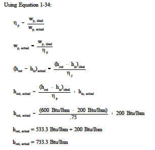
Example: A pump operating at 75% efficiency has an inlet specific enthalpy of 200 Btu/lbm. The exit specific enthalpy of the ideal pump is 600 Btu/lbm. What is the exit specific enthalpy of the actual pump?
Solution: Using Equation 1-34:
![]()
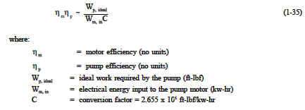
Pump efficiency, η p, relates the work required by an ideal pump to the actual work required by the pump; it relates the minimum amount of work theoretically possible to the actual work required by the pump. However, the work required by a pump is normally only an intermediate form of energy. Normally a motor or turbine is used to run the pump. Pump efficiency does not account for losses in this motor or turbine. An additional efficiency factor, motor efficiency ηm, is defined as the ratio of the actual work required by the pump to the electrical energy input to the pump motor, when both are expressed in the same units.

Like pump efficiency η p, motor efficiency η is always less than 1.0 or 100% for an actual pump motor. The combination of pump efficiency η p and motor efficiency ηmrelates the ideal pump to the electrical energy input to the pump motor.
A heat exchanger is designed to transfer heat between two working fluids. There are several heat exchangers used in power plant steam cycles. In the steam generator or boiler, the heat source (e.g., reactor coolant) is used to heat and vaporize the feed water. In the condenser, the steam exhausting from the turbine is condensed before being returned to the steam generator. In addition to these two major heat exchangers, numerous smaller heat exchangers are used throughout the steam cycle. Two primary factors determine the rate of heat transfer and the temperature difference between the two fluids passing through the heat exchanger.
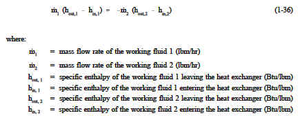
In the application of the first law general energy equation to a simple heat exchanger under steady flow conditions, it is found that the mass flow rates and enthalpies of the two fluids are related by the following relationship.
In the preceding sections we have discussed the Carnot cycle, cycle efficiencies, and component efficiencies. In this section we will apply this information to allow us to compare and evaluate various ideal and real cycles. This will allow us to determine how modifying a cycle will affect the cycle’s available energy that can be extracted for work.
Since the efficiency of a Carnot cycle is solely dependent on the temperature of the heat source and the temperature of the heat sink, it follows that to improve a cycles’ efficiency all we have to do is increase the temperature of the heat source and decrease the temperature of the heat sink. In the real world the ability to do this is limited by the following constraints.
- For a real cycle the heat sink is limited by the fact that the "earth" is our final heat sink. And therefore, is fixed at about 60°F (520°R).
- The heat source is limited to the combustion temperatures of the fuel to be burned or the maximum limits placed on nuclear fuels by their structural components (pellets, cladding etc.). In the case of fossil fuel cycles the upper limit is ~3040°F (3500°R). But even this temperature is not attainable due to the metallurgical restraints of the boilers, and therefore they are limited to about 1500°F (1960°R) for a maximum heat source temperature.
Using these limits to calculate the maximum efficiency attainable by an ideal Carnot cycle gives the following.
![]()
This calculation indicates that the Carnot cycle, operating with ideal components under real world constraints, should convert almost 3/4 of the input heat into work. But, as will be shown, this ideal efficiency is well beyond the present capabilities of any real systems.
Link to this Webpage:
© Copyright 2000 -
2024, by Engineers Edge, LLC
www.engineersedge.com
All rights reserved
Disclaimer |
Feedback
Advertising
| Contact