Rivet Application Tables and Installation Practice per. MIL-R-47196
General Engineering Reviews | Engineering Applications and Design
MIL-R-47196A, MILITARY SPECIFICATION: RIVETS, BUCK TYPE, PREPARATION FOR AND INSTALLATION OF (06-SEP-1977) [S/S BY NASM47196]. , This specification covers the preparation for and installation of buck rivets.
Rivet Installation.
-
a. All holes shall be drilled normal (at 90 degrees) to the working surface.
b. Extreme pressure shall not be applied and holes shall not be punched through with the drill.
c. When drilling through more than one sheet, hold the sheets securely together so there is no misalignment of holes due to shifting or separation of the sheets.
Piercing Only piercing tools which produce-true and clean holes, equivalent to acceptable drilled holes should be used. If piercing is used, all holes need be inspected for radial cracking.
Mating surfaces should be cleaned before parts are riveted together, all chips, burrs and foreign material must be removed from the mating surfaces. Burrs may be removed from rivet holes by chamfering to a depth not to exceed 10 percent of the stock thickness, or 0.032 inch, whichever is less.
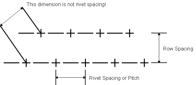
Oversize countersinks: When countersinks are enlarged beyond specified tolerances, the next larger size rivet may be used, provided pitch and edge margin design requirements are maintained. The term "next larger size" shall be defined as the next larger diameter for the application, but not to exceed 1/32 inch increments for sizes up to 1/4 inch diameter and 1/16 inch increments for sizes above 1/4 inch.
Repair limitations: The combined oversize rivet hole repairs and oversize countersink repairs should be limited to a maximum of 20 percent of the rivets, or 10 rivets in a single rivet pattern, whichever is less. Repairs to more than two adjacent oversize rivets, or replacing more than half the rivets with oversize rivets in any 10 inch length of pattern is prohibited.
| Rivet Diameter (inches) |
Recommended Drill Sizes |
Hole Diameter Limits |
|
|---|---|---|---|
Minimum |
Maximum |
||
| 1/16 |
#51 (0.067) |
0.062 |
0.072 |
| 3/32 |
#40 (0.098) |
0.093 |
0.103 |
| 1/8 |
#30 (0.128) |
0.125 |
0.135 |
| 5/32 |
#21 (0.159) #20 (0.161) |
0.156 |
0.171 |
| 3/16 |
#11 (0.191) #10 (0.194) |
0.187 |
0.202 |
| 7/32 |
#1 (0.228) |
0.218 |
0.233 |
| 1/4 |
F (0.257) |
0.250 |
0.265 |
| 9/32 |
L (0.290) |
0.281 |
0.296 |
| 5/16 |
0 (0.316) |
0.312 |
0.327 |
| 11/32 |
S (0.348) |
0.343 |
0.358 |
| 3/8 |
V (0.377) |
0.375 |
0.390 |
| 13/32 |
Z (0.413) |
0.406 |
0.421 |
Rivet Shank Unbucked Nominal Diameter |
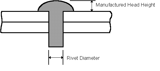
Minimum Manufactured Head Height (inches) |
|---|---|
| 1/16 |
0.022 |
3/32 |
0.032 |
1/8 |
0.042 |
5/32 |
0.052 |
3/16 |
0.062 |
7/32 ** |
0.072 |
1/4 |
0.083 |
9/32 ** |
0.093 |
5/16 |
0.104 |
11/32 ** |
0.114 |
3/8 |
0.125 |
13/32 ** |
0.135 |
** Indicates oversize replacements
Rivet Shank Unbucked Nominal Diameter |
Minimum Driven Head Diameter (inches) |
Driven Head Thickness (inches) |
|
|---|---|---|---|
Minimum |
Maximum |
||
1/16 |
0.081 |
0.025 |
0.040 |
3/32 |
0.122 |
0.038 |
0.050 |
1/8 |
0.163 |
0.050 |
0.070 |
5/32 |
0.203 |
0.062 |
0.092 |
3/16 |
0.244 |
0.075 |
0.105 |
7/32 ** |
0.285 |
0.087 |
0.110 |
1/4 |
0.325 |
0.100 |
0.130 |
9/32 ** |
0.365 |
0.113 |
0.140 |
5/16 |
0.406 |
0.125 |
0.158 |
11/32 ** |
0.450 |
0.137 |
0.170 |
3/8 |
0.488 |
0.150 |
0.190 |
13/32 ** |
0.530 |
0.165 |
0.200 |
** Indicates oversize replacements
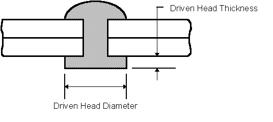
TABLE IV
Required Dimensions for Rivet Shaving (inches)
| Nominal Rivet Diameter | 1/16 | 3/32 | 1/8 | 5/32 | 3/16 | 7/32 | 1/4 | 9/32 | 5/16 | 11/32 | 3/8 | 13/32 |
|---|---|---|---|---|---|---|---|---|---|---|---|---|
| Maximum Head Protrusion Prior to Shaving ("H") | 0.005 | 0.006 | 0.007 | 0.009 | 0.010 | 0.011 | 0.012 | 0.013 | 0.014 | 0.015 | 0.016 | 0.017 |
| Minimum Head Diameter After Shaving ("D") | 0.095 | 0.161 | 0.204 | 0.262 | 0.326 | 0.383 | 0.443 | 0.490 | 0.526 | 0.588 | 0.650 | 0.712 |
| Nominal Rivet Diameter | 1/16 | 3/32 | 1/8 | 5/32 | 3/16 | 7/32 | 1/4 | 9/32 | 5/16 | 11/32 | 3/8 | 13/32 |
|---|---|---|---|---|---|---|---|---|---|---|---|---|
| Cutter Diameter | 3/8 | 3/8 | 3/8 | 3/8 | 7/16 | 1/2 | 9/16 | 9/16 | 5/8 | 5/8 | 3/4 | 3/4 |
| Nominal Rivet Diameter | 1/16 | 3/32 | 1/8 | 5/32 | 3/16 | 7/32 | 1/4 | 9/32 | 5/16 | 11/32 | 3/8 | 13/32 |
|---|---|---|---|---|---|---|---|---|---|---|---|---|
| Countersink Diameter | 0.110 | 0.176 | 0.222 | 0.284 | 0.351 | 0.411 | 0.474 | 0.522 | 0.560 | 0.625 | 0.690 | 0.756 |
Rivet Diameter (inches) |
Dimpled Countersunk Rivets |
Machine Countersunk Rivets |
Universal Head Rivets |
|---|---|---|---|
1/16 |
0.375 |
0.313 |
0.250 |
3/32 |
0.563 |
0.438 |
0.375 |
1/8 |
0.625 |
0.531 |
0.500 |
5/32 |
0.688 |
0.625 |
0.563 |
3/16 |
0.750 |
0.750 |
0.688 |
7/32 ** |
0.875 |
0.875 |
0.0781 |
1/4 |
0.938 |
1.375 |
0.875 |
9/32 ** |
1.125 |
1.125 |
1.000 |
5/16 |
1.250 |
1.250 |
1.125 |
11/32 |
1.375 |
1.375 |
1.250 |
3/8 |
1.500 |
1.500 |
1.344 |
13/32 ** |
1.625 |
1.625 |
1.469 |
** indicates sizes normally used for oversize replacement only
Rivet Diameter (inches) |
Minimum A and B |
Minimum C and D |
|---|---|---|
1/16 |
0.094 |
0.156 |
3/32 |
0.156 |
0.219 |
1/8 |
0.219 |
0.281 |
5/32 |
0.281 |
0.344 |
3/16 |
0.344 |
0.375 |
7/32 ** |
0.406 |
0.438 |
1/4 |
0.438 |
0.500 |
9/32 ** |
0.500 |
0.563 |
5/16 |
0.563 |
0.625 |
11/32 |
0.625 |
0.688 |
3/8 |
0.688 |
0.750 |
13/32 ** |
0.750 |
0.812 |
** indicates sizes normally used for oversize replacement only
Typical Examples of Unacceptable Rivets
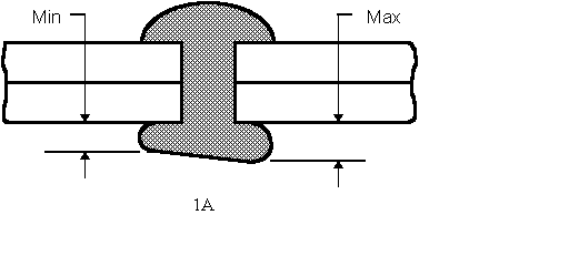
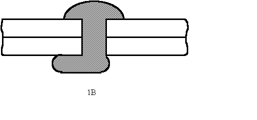
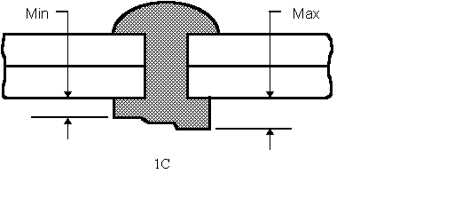
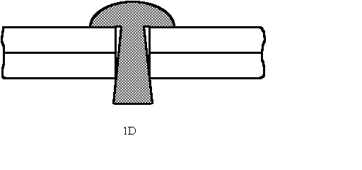
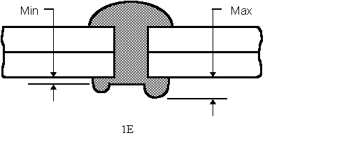
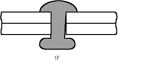
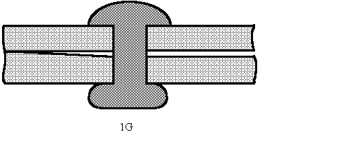
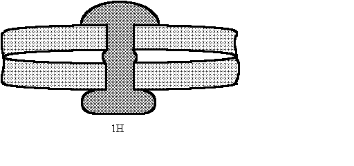
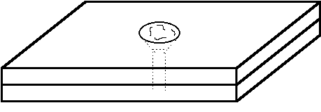
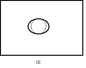
FIGURE 2
Minimum Edge Margins
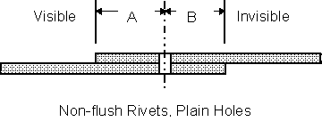
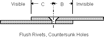
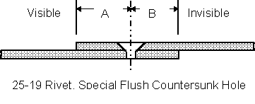
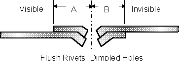
Special Considerations
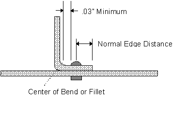
Provide a minimum of .03" between the edge of non-flush rivet heads (Nos. 1 or 2) and bend radius tangent point. Otherwise, maintain the normal edge distances, both visible and invisible.
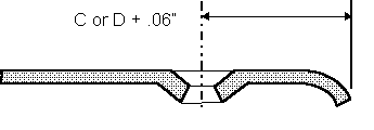
When the design calls for crimped sheet edges in conjunction with dimpled holes, add .06" to values indicated for flush rivets. This is to provide clearance for the crimping tool.