Related Resources: material science
Structural Composite Sandwich Design and Analysis in Aerospace Applications
Structural Composite Sandwich Design and Analysis in Aerospace Applications
Structural sandwich is a layered composite, formed by bonding two thin facings to a thick core. It is a type of stressed-skin construction in which the facings resist nearly all of the applied edgewise (in-plane) loads and flat wise bending moments. The thin spaced facings provide nearly all of the bending rigidity to the construction. The core spaces the facings and transmits shear between them so that they are effective about a common neutral axis. The core also provides most of the shear rigidity of the sandwich construction. By proper choice of materials for facings and core J constructions with high ratios of stiffness to weight can be achieved.
A basic design concept is to space strong, thin facings far enough apart to achieve a high ratio of stiffness to weight; the lightweight core that does this also provides the required resistance to shear and is strong enough to stabilize the facings to their desired configuration through a bonding media such as an adhesive layer, braze or weld. The sandwich is analogous to an I-beam in which the flanges carry direct compression and tension loads, as do the sandwich facings, and the web carries shear loads, as does the sandwich core.
In order that sandwich cores be lightweight they are usually made of low density material, some type of cellular construction (honeycomb like core formed of thin sheet material) or of corrugated sheet material. As a consequence of employing a lightweight core, design methods account for core shear deformation because of the low effective shear modulus of the core. The main difference in design procedures for sandwich structural elements as compared to design procedures for homogeneous material is the inclusion of the effects of core shear properties on deflection, buckling and stress for the sandwich.
Because thin facings can be used to carry loads in a sandwich, prevention of local failure under edgewise direct or flat wise bending loads is necessary just as prevention of local crippling of adjoining stringers is necessary in the design of sheet stringer construction. Modes of failures that may occur in sandwich under edge load are shown in Figure 1A - 1D.
Shear crimping failure, as shown in Figure 1B, appears to be a local mode of failure, but is actually a form of general overall buckling in which the wavelength of the buckles is very small because of low core shear modulus. The crimping of the sandwich occurs suddenly and usually causes the core to fail in shear at the crimp; it may also cause shear failure in the bond between the facing and core.
Crimping may also occur in cases where the overall buckle begins to appear and then the crimp occurs suddenly because of severe local shear stresses at the ends of the overall buckle. As soon as the crimp appears the overall buckle may disappear. Therefore. although examination of a failed sandwich indicates crimping or shear instability, failure may have begun by overall buckling that finally caused crimping.
If the core is of cellular (honeycomb) or corrugated material, it is possible for the facings to buckle or dimple into the spaces between core walls or corrugations as shown in Figure 1A and 1C.
Dimpling may be severe enough so that permanent dimples remain after removal of load and the amplitude of the dimples may be large enough to cause the dimples to grow across the cell walls and result in a wrinkling of the facings.
Wrinkling, as shown in Figure 1D, may occur if a sandwich facing is subjected to edgewise compression buckles as a plate on an elastic foundation. The facing may buckle inward or outward depending on the flat wise compressive strength of the core relative to the flat wise tensile strength of the bond between the facing and core. If the bond between facing and core is strong, facings can wrinkle and cause tension failure in the core. Thus, the wrinkling load depends upon the elasticity and strength of the foundation system; namely the core and the bond between facing and core. Since the facing is never perfectly flat, the wrinkling load will also depend upon the initial eccentricity of the facing or original waviness.
The local modes of failure may occur in sandwich panels under edgewise loads or normal loads. In addition to overall buckling and local modes of failure, sandwich is designed so that facings do not fail in tension, compression, shear or combined stresses due to edgewise loads or normal loads and cores and bonds do not fail in shear, flat wise tension or flat wise compression due to normal loads.
The basic design principles can be summarized into four conditions as follows:
(1) Sandwich facings should be at least thick enough to withstand chosen design stresses under design loads .
(2) The core should be thick enough and have sufficient shear rigidity and strength so that overall sandwich buckling, excessive deflection and shear failure will not occur under design loads.
(3) The core should have high enough modulus of elasticity and the sandwich shall have great enough flatwise tensile and compressive strength so that wrinkling of either facing will not occur under design loads.
(4) If the core is cellular (honeycomb) or of corrugated material and dimpling of the faces is not permissible, the cell size or corrugation spacing shall be small enough so that dimpling of either facing into the core spaces will not occur under design loads.
The facing to core bond should have sufficient flatwise tensile and shear strength to develop the core strength in the expected environment. The environment includes effects of temperature, water or moisture, corrosive atmosphere and fluids, fatigue, creep and any other condition that affects material properties.
The following Figure 1A - 1D are the possible modes of failure of sandwich under edgewise compression.
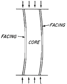
Fugire 1A - General Buckling
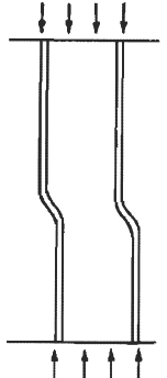
Figure 1B - Shear Crimping
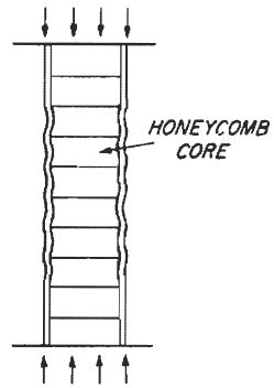
Figure 1C - Dimpling of Facings
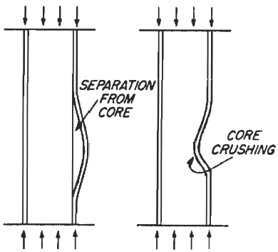
Figure 1D - Wrinking of Facings
Source
Bell Helicopter Structural Design Manual, 1977
Related
- Advanced Composites Design and Applications
- Short Fiber Plastic Base Composites Engineering Design Handbook
- Fibrous Composites Design and Analysis
- Joints in Polymeric Composites
- Concurrent Engineering For Composites
- Composite Engineering Materials Review
- Joining of Advanced Composites Engineering Design Handbook
- Composites Materials Handbook, Volume 1
- Polymer Matrix Composites Materials Handbook, Volume 2
- Composites Material Usage, Design, and Analysis Handbook, Volume 3
- Metal Matrix Composites Handbook, Volume 4
- Ceramic Matrix Composites Design Handbook, Volume 5
- Design for Machining Fiberglass and Composites
- Honeycomb Beam Spreadsheet Calculator
- Intracell Buckling Honeycomb Sandwich Panels Excel Calculator
Link to this Webpage:
© Copyright 2000 -
2024, by Engineers Edge, LLC
www.engineersedge.com
All rights reserved
Disclaimer |
Feedback
Advertising
| Contact