Related Resources: material science
Free Body Diagram
A free body diagram, is a drawing, sketch or diagram used illustrate and analyze the physics related forces and moments acting on an object.
The object may be an assembly of many components or parts or just a sectional two-dimensional view of a component, such a W-flange beam or a diagramed fluid system. A series of such free body diagrams may be required to fully analyze the reactive forces in a complex application. The free body in a free body diagram is not free of constraints, it is just that the constraints have been replaced by arrows representing the forces and moments they generate.
 |
What is normally required in a Free Body Diagram?
In general, the free body diagram is created to represent the component of interest and the external forces acting on it, such as,
1. The body: This is usually sketched in a schematic way depending on the body - particle/extended, rigid/non-rigid - and on what questions are to be answered. Therefore, if rotation of the body and torque is in consideration, an indication of size and shape of the body is needed. For example the reactive forces of a automotive brake disk cannot be found from a single point, and a sketch with finite dimensions is required.
2. The external forces: These are indicated by labeled arrows. In a fully solved problem, a force arrow is capable of indicating
(i) the direction and the line of action
(ii) the magnitude
(iii) the point of application.
Typically, an initial free body sketch is drawn before all acting forces and components are known. For example when a force arrow is drawn on the free body diagram its length may not be meant to indicate the unknown magnitude. Its line may not correspond to the exact line of action. Even its direction may turn out to wrong. Very often the original direction of the arrow may be directly opposite to the true direction. An engineer may also omit some forces altogether, especially in rigid body analysis where there are paired forces which cancel each other.
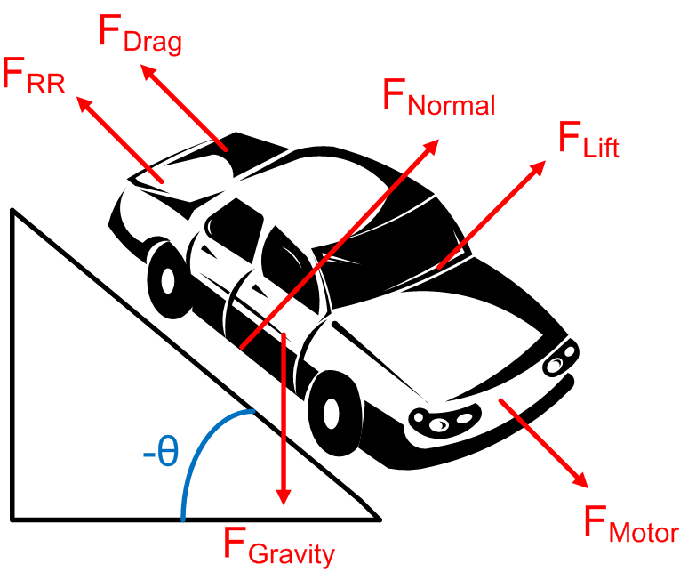
The forces acting on the component may include; friction, gravity, normal force, drag, tension, compression, or a combination of these forces. When in a non-inertial reference frame, fictitious forces, such as centrifugal pseudo force may be appropriate.
A coordinate system maybe require as well, depending on the complexity or diagram requirements. The coordinate system may make defining the vectors simpler when writing the equations of motion. The x direction might be chosen to point down the ramp in an inclined plane problem, for example. In that case the friction force only has an x component, and the normal force only has a y component. The force of gravity will still have components in both the x and y direction: mgsin(θ) in the x and mgcos(θ) in the y, where θ is the angle between the ramp and the horizontal.
Link to this Webpage:
© Copyright 2000 -
2024, by Engineers Edge, LLC
www.engineersedge.com
All rights reserved
Disclaimer |
Feedback
Advertising
| Contact