Potentiometer Position Indicator Review
Electronics, Instrumentation & Electrical Database
Potentiometer Position Indicator Review
A potentiometer, informally a pot, is a three-terminal resistor with a sliding or rotating contact that forms an adjustable voltage divider. If only two terminals are used, one end and the wiper, it acts as a variable resistor or rheostat.
A potentiometer measuring instrument is essentially a voltage divider used for measuring electric potential (voltage); the component is an implementation of the same principle, hence its name.
Potentiometers are commonly used to control electrical devices such as volume controls on audio equipment. Potentiometers operated by a mechanism can be used as position transducers, for example, in a joystick. Potentiometers are rarely used to directly control significant power (more than a watt), since the power dissipated in the potentiometer would be comparable to the power in the controlled load.
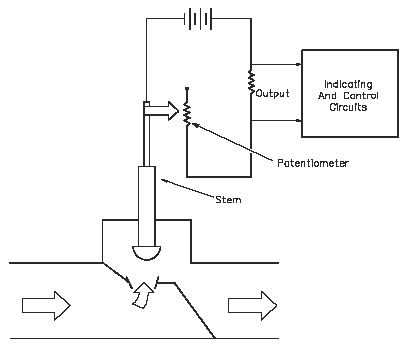
Potentiometer valve position indicators (Figure F1) provide an accurate indication of position throughout the travel of a valve or control rod. The extension is physically attached to a variable resistor. As the extension moves up or down, the resistance of the attached circuit changes, changing the amount of current flow in the circuit. The amount of current is proportional to the valve position.

Figure F1
Potentiometer valve position indicator failures are normally electrical in nature. An electrical short or open will cause the indication to fail at one extreme or the other. If an increase or decrease in the potentiometer resistance occurs, erratic indicated valve position occurs.
Potentiometers Construction
Potentiometers comprise a resistive element, a sliding contact (wiper) that moves along the element, making good electrical contact with one part of it, electrical terminals at each end of the element, a mechanism that moves the wiper from one end to the other, and a housing containing the element and wiper.
Many inexpensive potentiometers are constructed with a resistive element formed into an arc of a circle usually a little less than a full turn and a wiper sliding on this element when rotated, making electrical contact. The resistive element, with a terminal at each end, is flat or angled. The wiper is connected to a third terminal, usually between the other two. On panel potentiometers, the wiper is usually the center terminal of three. For single-turn potentiometers, this wiper typically travels just under one revolution around the contact. The only point of ingress for contamination is the narrow space between the shaft and the housing it rotates in.
Another type is the linear slider potentiometer, which has a wiper which slides along a linear element instead of rotating. Contamination can potentially enter anywhere along the slot the slider moves in, making effective sealing more difficult and compromising long-term reliability. An advantage of the slider potentiometer is that the slider position gives a visual indication of its setting. While the setting of a rotary potentiometer can be seen by the position of a marking on the knob, an array of sliders can give a visual impression of, for example, the effect of a multi-band equaliser (hence the term "graphic equaliser").
The resistive element of inexpensive potentiometers is often made of graphite. Other materials used include resistance wire, carbon particles in plastic, and a ceramic/metal mixture called cermet. Conductive track potentiometers use conductive polymer resistor pastes that contain hard-wearing resins and polymers, solvents, and lubricant, in addition to the carbon that provides the conductive properties.
Others are enclosed within the equipment and are intended to be adjusted to calibrate equipment during manufacture or repair, and not otherwise touched. They are usually physically much smaller than user-accessible potentiometers, and may need to be operated by a screwdriver rather than having a knob. They are usually called "preset potentiometers" or "trim[ming] pots". Some presets are accessible by a small screwdriver poked through a hole in the case to allow servicing without dismantling.
Multiturn potentiometers are also operated by rotating a shaft, but by several turns rather than less than a full turn. Some multiturn potentiometers have a linear resistive element with a sliding contact moved by a lead screw; others have a helical resistive element and a wiper that turns through 10, 20, or more complete revolutions, moving along the helix as it rotates. Multiturn potentiometers, both user-accessible and preset, allow finer adjustments; rotation through the same angle changes the setting by typically a tenth as much as for a simple rotary potentiometer.
A string potentiometer is a multi-turn potentiometer operated by an attached reel of wire turning against a spring, enabling it to convert linear position to a variable resistance.
User-accessible rotary potentiometers can be fitted with a switch which operates usually at the anti-clockwise extreme of rotation. Before digital electronics became the norm such a component was used to allow radio and television receivers and other equipment to be switched on at minimum volume with an audible click, then the volume increased, by turning a knob. Multiple resistance elements can be ganged together with their sliding contacts on the same shaft, for example, in stereo audio amplifiers for volume control. In other applications, such as domestic light dimmers, the normal usage pattern is best satisfied if the potentiometer remains set at its current position, so the switch is operated by a push action, alternately on and off, by axial presses of the knob.