Hydraulic Shock Absorbers Review
Hydraulic and Pneumatic Knowledge
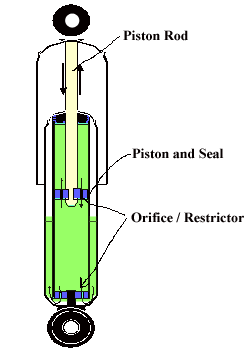
Hydraulic Shock Absorbers utilize liquid fluid to convert mechanical energy into thermal energy. The dampening or shock absorber action is facilitated by the shock absorber's fluid being displaced by a piston displaced by mechanical action that forces the fluid through a orifice(s) or flow restrictor(s).
 Linear Hydraulic Shock Absorber |
The orifices which the fluid passes through limits the velocity or volume flow and converts the fluid (mechanical) energy into thermal energy within the hydraulic fluid The heat energy is then transferred through the fluid and out the devices mechanical mass to the ambient air or environment.
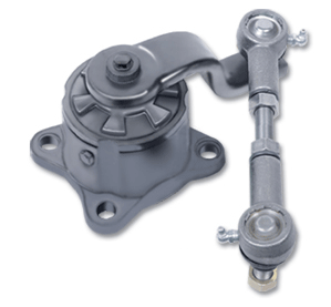
Hydraulic shock absorbers are designed to dampened linear, rotary and other movement configurations.
Hydraulic Shock absorbers are utilized within automobile, agriculture equipment, motorcycle suspensions, heavy truck, aircraft landing gear, conveyor systems, structural engineering applications, and many other custom industrial applications. Large hydraulic shock absorbers have been used within structural engineering (buildings, and critical industrial equipment) to reduce the vulnerability of the structures and installations to seismic damage and resonance.
Application and Selection: Determining the correct hydraulic shock absorber size and performance chaacteristics requires a complete understanding of the dynamic and static requirements of the mechanical system targeted. The goal of the system component designers is to properly determine the energy input requirements the shock absorber will manage and at the velocity the shock absorber device will operate at. Performance requirements of a shock absorber system should be accurately understood, or conservatively estimated. A shock absorber that "bottoms-out" or impacts internal static stops because of insufficient energy capacity will result in the supporting structure of the shock absorbing the energy overage and may result in possible damage to the shock absorber or supporting structure. Regardless of how the engineer/designer determine shock absorber size and installation application, a functional test should be performed to verify performance.
The following will need to be determined:
- Velocity and stroke of target application.
- Kinetic Energy.
- Static and dynamic force at hydraulic shock absorber.
- Number, installation, and configuration of shock absorbers required.
- Deceleration rate of shock absorber Size.
- Deceleration time for shock to stroke.
- Cycles (maximum) per minute or lifecycle of component.
Rotary Hydraulic Shock Absorber |
Note that the mechanical absorption or damping action can be in compression or during extension.
To solve for velocity of simple mechanisms:
Hydraulic Cylinder Drive:
V = 1.5 [Average Cylinder Velocity (ft/sec.)]
Mechanisms with constant acceleration and known time (duty cycle):
V = aT
Mechanisms with initial velocity (VO, Ft/Sec.) plus constant
Acceleration And Known Time
V = VO + aT
Mechanism with constant acceleration and known distance (Ft.) to gain velocity:
V2 = 2 (a) (distance)
Kinetic Energy of Simple Systems:
Horizontal motion
KE = .1865 WV2
Vertical motion
KE = W (H + S)
Rotary motion
KE = 6 I V2R
All of the above equation are for simple applications. Complex systems are beyond the scope and intent of this review. Always consult an engineering specialist or expert when designing for complex shock absorber applications.
Where:
KE = Kinetic energy (in-lb.)
W = Weight (lb.)
V = Linear velocity of impact at the shock absorber (ft/sec.)
VR = Rotational velocity of impact (radians/sec.) at the shock absorber
H = Height (in.)
S = Stroke (in.)
I = Moment of Inertia (lb-ft-sec2)
T = Time (sec.)
a = Acceleration (ft/sec.2)
