Related Resources: hardware
Tapered Shaft End and Mating Hole Design
ANSI Hardware Deign and Engineering Data
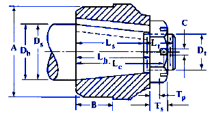 |
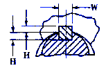 Taper per Ft. = 1.500 ± 0.002 H is measured Perpendicular to key C, Cotter Pin Hole has centerline Displaced 90° From Keyway Center |
Tapered Shaft End and Mating Hole with Slotted Nuts Design Data Dimensions Per. SAE Standard
All dimensions are given in inch units
|
Nom.
Dia. |
Dia. of
Shaft, Ds |
Dia. of
Hole, Dh |
Lc
|
Ls
|
Lh
|
Lt
|
Ts
|
Tp
|
Nut Width,
Flats |
||
|
Max.
|
Min.
|
Max.
|
Min.
|
||||||||
|
1⁄4
|
0.250
|
0.249
|
0.248
|
0.247
|
9⁄16
|
5⁄16
|
3⁄8
|
5⁄16
|
7⁄32
|
9⁄64
|
5⁄16
|
|
3⁄8
|
0.375
|
0.374
|
0.373
|
0.372
|
47⁄64
|
7⁄16
|
1⁄2
|
23⁄64
|
17⁄64
|
3⁄16
|
1⁄2
|
|
1⁄2
|
0.500
|
0.499
|
0.498
|
0.497
|
63⁄64
|
11⁄16
|
3⁄4
|
23⁄64
|
17⁄64
|
3⁄16
|
1⁄2
|
|
5⁄8
|
0.625
|
0.624
|
0.623
|
0.622
|
13⁄32
|
11⁄16
|
3⁄4
|
17⁄32
|
7⁄16
|
1⁄4
|
3⁄4
|
|
3⁄4
|
0.750
|
0.749
|
0.748
|
0.747
|
111⁄32
|
15⁄16
|
1
|
17⁄32
|
7⁄16
|
1⁄4
|
3⁄4
|
|
7⁄8
|
0.875
|
0.874
|
0.873
|
0.872
|
111⁄16
|
11⁄8
|
11⁄4
|
11⁄16
|
1⁄2
|
5⁄16
|
15⁄16
|
|
1
|
1.001
|
0.999
|
0.997
|
0.995
|
115⁄16
|
13⁄8
|
11⁄2
|
11⁄16
|
1⁄2
|
5⁄16
|
11⁄16
|
|
1 1⁄8
|
1.126
|
1.124
|
1.122
|
1.120
|
115⁄16
|
13⁄8
|
11⁄2
|
11⁄16
|
1⁄2
|
5⁄16
|
11⁄4
|
|
1 1⁄4
|
1.251
|
1.249
|
1.247
|
1.245
|
115⁄16
|
13⁄8
|
11⁄2
|
11⁄16
|
1⁄2
|
5⁄16
|
17⁄16
|
|
1 3⁄8
|
1.376
|
1.374
|
1.372
|
1.370
|
27⁄16
|
17⁄8
|
2
|
11⁄16
|
1⁄2
|
5⁄16
|
17⁄16
|
|
1 1⁄2
|
1.501
|
1.499
|
1.497
|
1.495
|
27⁄16
|
17⁄8
|
2
|
11⁄16
|
1⁄2
|
5⁄16
|
17⁄16
|
|
1 5⁄8
|
1.626
|
1.624
|
1.622
|
1.620
|
213⁄16
|
21⁄8
|
21⁄4
|
13⁄16
|
5⁄8
|
7⁄16
|
23⁄16
|
|
1 3⁄4
|
1.751
|
1.749
|
1.747
|
1.745
|
213⁄16
|
21⁄8
|
21⁄4
|
13⁄16
|
5⁄8
|
7⁄16
|
23⁄16
|
|
1 7⁄8
|
1.876
|
1.874
|
1.872
|
1.870
|
31⁄16
|
23⁄8
|
21⁄2
|
13⁄16
|
5⁄8
|
7⁄16
|
23⁄16
|
|
2
|
2.001
|
1.999
|
1.997
|
1.995
|
39⁄16
|
27⁄8
|
3
|
13⁄16
|
5⁄8
|
7⁄16
|
23⁄16
|
|
2 1⁄4
|
2.252
|
2.248
|
2.245
|
2.242
|
39⁄16
|
27⁄8
|
3
|
13⁄16
|
5⁄8
|
7⁄16
|
23⁄8
|
|
2 1⁄2
|
2.502
|
2.498
|
2.495
|
2.492
|
49⁄32
|
33⁄8
|
31⁄2
|
11⁄4
|
1
|
5⁄8
|
31⁄8
|
|
2 3⁄4
|
2.752
|
2.748
|
2.745
|
2.742
|
49⁄32
|
33⁄8
|
31⁄2
|
11⁄4
|
1
|
5⁄8
|
31⁄8
|
|
3
|
3.002
|
2.998
|
2.995
|
2.992
|
225⁄32
|
37⁄8
|
4
|
11⁄4
|
1
|
5⁄8
|
31⁄8
|
|
3 1⁄4
|
3.252
|
3.248
|
3.245
|
3.242
|
51⁄32
|
41⁄8
|
41⁄4
|
11⁄4
|
1
|
5⁄8
|
31⁄8
|
|
3 1⁄2
|
3.502
|
3.498
|
3.495
|
3.492
|
57⁄16
|
43⁄8
|
41⁄2
|
13⁄8
|
11⁄8
|
3⁄4
|
37⁄8
|
|
4
|
4.002
|
3.998
|
3.995
|
3.992
|
67⁄16
|
53⁄8
|
51⁄2
|
13⁄8
|
11⁄8
|
3⁄4
|
37⁄8
|
Waaodruff Keyway Design Dimensional Data for Tapered Shaft
|
Nom.
Dia. |
Dt
|
Thds. per
Inch |
Keyway
|
Square Key
|
A
|
B
|
C
|
||||
|
W
|
H
|
||||||||||
|
Max.
|
Min.
|
Max.
|
Min.
|
Max.
|
Min.
|
||||||
|
1⁄4
|
#10
|
40
|
0.0625
|
.0615
|
.037
|
.033
|
0.0635
|
0.0625
|
1⁄2
|
3⁄16
|
5⁄64
|
|
3⁄8
|
5⁄16
|
32
|
0.0937
|
.0927
|
.053
|
.049
|
0.0947
|
0.0937
|
11⁄16
|
1⁄4
|
5⁄64
|
|
1⁄2
|
5⁄16
|
32
|
0.1250
|
.1240
|
.069
|
.065
|
0.1260
|
0.1250
|
7⁄8
|
3⁄8
|
5⁄64
|
|
5⁄8
|
1⁄2
|
28
|
0.1562
|
.1552
|
.084
|
.080
|
0.1572
|
0.1562
|
11⁄16
|
3⁄8
|
1⁄8
|
|
3⁄4
|
1⁄2
|
28
|
0.1875
|
.1865
|
.100
|
.096
|
0.1885
|
0.1875
|
11⁄4
|
5⁄8
|
1⁄8
|
|
7⁄8
|
5⁄8
|
24
|
0.2500
|
.2490
|
.131
|
.127
|
0.2510
|
0.2500
|
11⁄2
|
3⁄4
|
5⁄32
|
|
1
|
3⁄4
|
20
|
0.2500
|
.2490
|
.131
|
.127
|
0.2510
|
0.2500
|
13⁄4
|
7⁄8
|
5⁄32
|
|
1 1⁄8
|
7⁄8
|
20
|
0.3125
|
.3115
|
.162
|
.158
|
0.3135
|
0.3125
|
2
|
7⁄8
|
5⁄32
|
|
1 1⁄4
|
1
|
20
|
0.3125
|
.3115
|
.162
|
.158
|
0.3135
|
0.3125
|
21⁄8
|
7⁄8
|
5⁄32
|
|
1 3⁄8
|
1
|
20
|
0.3750
|
.3740
|
.194
|
.190
|
0.3760
|
0.3750
|
21⁄4
|
1
|
5⁄32
|
|
1 1⁄2
|
1
|
20
|
0.3750
|
.3740
|
.194
|
.190
|
0.3760
|
0.3750
|
21⁄2
|
1
|
5⁄32
|
|
1 5⁄8
|
1 1⁄4
|
18
|
0.4375
|
.4365
|
.225
|
.221
|
0.4385
|
0.4375
|
2 3⁄4
|
1 1⁄4
|
5⁄32
|
|
1 3⁄4
|
1 1⁄4
|
18
|
0.4375
|
.4365
|
.225
|
.221
|
0.4385
|
0.4375
|
3
|
1 1⁄4
|
5⁄32
|
|
1 7⁄8
|
1 1⁄4
|
18
|
0.4375
|
.4365
|
.225
|
.221
|
0.4385
|
0.4375
|
3 1⁄8
|
1 1⁄4
|
5⁄32
|
|
2
|
1 1⁄4
|
18
|
0.5000
|
.4990
|
.256
|
.252
|
0.5010
|
0.5000
|
3 1⁄4
|
1 1⁄2
|
5⁄32
|
|
2 1⁄4
|
1 1⁄2
|
18
|
0.5625
|
.5610
|
.287
|
.283
|
0.5640
|
0.5625
|
3 1⁄2
|
1 1⁄2
|
5⁄32
|
|
2 1⁄2
|
2
|
16
|
0.6250
|
.6235
|
.319
|
.315
|
0.6265
|
0.6250
|
4
|
1 3⁄4
|
7⁄32
|
|
2 3⁄4
|
2
|
16
|
0.6875
|
.6860
|
.350
|
.346
|
0.6890
|
0.6875
|
4 3⁄8
|
1 3⁄4
|
7⁄32
|
|
3
|
2
|
16
|
0.7500
|
.7485
|
.381
|
.377
|
0.7515
|
0.7500
|
4 3⁄4
|
2
|
7⁄32
|
|
3 1⁄4
|
2
|
16
|
0.7500
|
.7485
|
.381
|
.377
|
0.7515
|
0.7500
|
5
|
2 1⁄8
|
7⁄32
|
|
3 1⁄2
|
2 1⁄2
|
16
|
0.8750
|
.8735
|
.444
|
.440
|
0.8765
|
0.8750
|
5 1⁄2
|
2 1⁄4
|
9⁄32
|
|
4
|
2 1⁄2
|
16
|
1.0000
|
.9985
|
.506
|
.502
|
1.0015
|
1.0000
|
6 1⁄4
|
2 3⁄4
|
9⁄32
|
All dimensions in inches except where otherwise noted.
Link to this Webpage:
© Copyright 2000 -
2024, by Engineers Edge, LLC
www.engineersedge.com
All rights reserved
Disclaimer |
Feedback
Advertising
| Contact