Related Resources: hardware
Sheet Metal Thread Dimensions for Types AB, A and U Thread Forming Tapping Screws
ANSI Hardware Design and Application Guide
ISO Metric Hardware Engineering and Design Data
Fastener and Screw / Bolt Design, Formula & Calculations
Sheet Metal Thread Dimensions for Types AB, A and U Thread Forming Tapping Screws per. ANSI B18.6.4 and ASTM F593
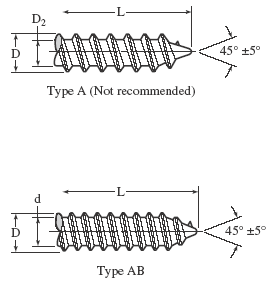
Type A: Spaced-thread screw with gimlet point primarily for use in light sheet metal, resin-impregnated plywood, and asbestos compositions. This type is no longer recommended.
Use Type AB in new designs and whenever possible substitute for Type A in existing designs.
Type AB: Spaced-thread screw with same pitches as Type B but with gimlet point, primarily for similar uses as for Type A.
Type U: Multiple-threaded drive screw with large helix angle, having a pilot point, for use in metal and plastics. This screw is forced into the work by pressure and is intended for making permanent fastenings.
Designation. Sheet metal and tapping screws are designated by the following data in the sequence shown: Nominal size (number, fraction or decimal equivalent); threads per inch; nominal length (fraction or decimal equivalent); point type; product name, including head type and driving provision; material; and protective finish, if required.
Examples:
1⁄4-14 × 11⁄2 Type AB Slotted Pan Head Tapping Screw, Steel, Nickel Plate,d
6-32 × 3⁄4 Type T, Type 1A Cross Recessed Pan Head Tapping Screw, Corrosion Resistant
Stee,l
0.375-16 × 1.50 Type D, Washer Head Tapping Screw, Steel
Type AB (Formerly BA) |
|||||
Nominal Size - Basic Screw Dia. |
Threads per inch |
D |
d |
||
Major Diameter |
Minor Diameter |
||||
Max. |
Min. |
Max. |
Min. |
||
0 - 0.0600 |
48 |
0.060 |
0.054 |
0.036 |
0.033 |
1 - 0.0730 |
42 |
0.075 |
0.069 |
0.049 |
0.046 |
|
2 - 0.0860 |
32 |
0.088 |
0.082 |
0.064 |
0.060 |
3 - 0.0990 |
28 |
0.101 |
0.095 |
0.075 |
0.071 |
|
4 - 0.1120 |
24 |
0.114 |
0.108 |
0.086 |
0.082 |
5 - 0.1250 |
20 |
0.130 |
0.123 |
0.094 |
0.090 |
|
6 - 0.1380 |
20 |
0.139 |
0.132 |
0.104 |
0.099 |
7 - 0.1510 |
19 |
0.154 |
0.147 |
0.115 |
0.109 |
|
8 - 0.1640 |
18 |
0.166 |
0.159 |
0.122 |
0.116 |
|
10 - 0.1900 |
16 |
0.189 |
0.182 |
0.141 |
0.135 |
12 - 0.2160 |
14 |
0.215 |
0.208 |
0.164 |
0.157 |
1⁄4 - 0.2500 |
14 |
0.246 |
0.237 |
0.192 |
0.185 |
5⁄16 - 0.3125 |
12 |
0.315 |
0.306 |
0.244 |
0.236 |
3⁄8 - 0.3750 |
12 |
0.380 |
0.371 |
0.309 |
0.299 |
7⁄16 - 0.4375 |
10 |
0.440 |
0.429 |
0.359 |
0.349 |
1⁄2 - 0.5000 |
10 |
0.504 |
0.493 |
0.423 |
0.413 |
Type A |
|||||
Nominal Sizea - Basic Screw Diameter |
Threads per inch |
D |
d |
||
Major Diameter |
Minor Diameter |
||||
Max. |
Min. |
Max. |
Min. |
||
0 - 0.0600 |
40 |
0.060 |
0.057 |
0.042 |
0.039 |
1 - 0.0730 |
32 |
0.075 |
0.072 |
0.051 |
0.048 |
2 - 0.0860 |
32 |
0.088 |
0.084 |
0.061 |
0.056 |
3 - 0.0990 |
28 |
0.101 |
0.097 |
0.076 |
0.071 |
4 - 0.1120 |
24 |
0.114 |
0.110 |
0.083 |
0.078 |
5 - 0.1250 |
20 |
0.130 |
0.126 |
0.095 |
0.090 |
6 - 0.1380 |
18 |
0.141 |
0.136 |
0.102 |
0.096 |
7 - 0.1510 |
16 |
0.158 |
0.152 |
0.114 |
0.108 |
8 - 0.1640 |
15 |
0.168 |
0.162 |
0.123 |
0.116 |
10 - 0.1900 |
12 |
0.194 |
0.188 |
0.133 |
0.126 |
12 - 0.2160 |
11 |
0.221 |
0.215 |
0.162 |
0.155 |
14 - 0.2420 |
10 |
0.254 |
0.248 |
0.185 |
0.178 |
16 - 0.2680 |
10 |
0.280 |
0.274 |
0.197 |
0.189 |
18 - 0.2940 |
9 |
0.306 |
0.300 |
0.217 |
0.209 |
20 - 0.3200 |
9 |
0.333 |
0.327 |
0.234 |
0.226 |
24 - 0.3720 |
9 |
0.390 |
0.383 |
0.291 |
0.282 |
a Where specifying nominal size in decimals, zeros preceding decimal and in fourth place are omited
Type U Metallic Drive Screws |
|||||||||||
Nom. Size |
No. of Starts |
Out. Dia. |
Pilot Dia. |
Nom. Size |
No. of Starts |
Out. Dia. |
Pilot Dia. |
||||
Max. |
Min. |
Max. |
Min. |
Max. |
Min. |
Max. |
Min. |
||||
00 |
6 |
0.060 |
0.057 |
0.049 |
0.046 |
8 |
8 |
0.167 |
0.162 |
0.136 |
0.132 |
0 |
6 |
0.075 |
0.072 |
0.063 |
0.060 |
10 |
8 |
0.182 |
0.177 |
0.150 |
0.146 |
2 |
8 |
0.100 |
0.097 |
0.083 |
0.080 |
12 |
8 |
0.212 |
0.206 |
0.177 |
0.173 |
4 |
7 |
0.116 |
0.112 |
0.096 |
0.092 |
14 |
9 |
0.242 |
0.236 |
0.202 |
0.198 |
6 |
7 |
0.140 |
0.136 |
0.116 |
0.112 |
5⁄16 |
11 |
0.315 |
0.309 |
0.272 |
0.267 |
7 |
8 |
0.154 |
0.150 |
0.126 |
0.122 |
3⁄8 |
12 |
0.378 |
0.371 |
0.334 |
0.329 |
All dimensions are in inches. See image above for thread diagrams. Type A screws are no longer recommended.
Related
- Maximum tightening torque for metric self tapping screws
- Self Tapping Screw Pull-Out and Torque Calculator
- Self Tapping Screw Pull-Out and Torque Calculator
- Self Tapping Screws Installation Design | Engineering
Link to this Webpage:
© Copyright 2000 -
2024, by Engineers Edge, LLC
www.engineersedge.com
All rights reserved
Disclaimer |
Feedback
Advertising
| Contact