Related Resources: hardware
Internal Self-Locking Retaining Rings Thrust Load Capacity
ANSI Hardware Design Guide and Charts
Thrust Load Capacity of Inch Series Internal Self-Locking Retaining Rings
Internal Rings: Thrust loads are for rings made of standard material inserted into cold-rolled, low carbon housing. Ring Thickness Tolerances: For housing sizes 0.311 through 0.627, ±0.001; for sizes 0.748 through 1.502, ±0.002. Ring Diameter Tolerances: For housing sizes 0.311 through 0.439, ±0.005; for sizes 0.498 through 1.502, ±0.010.
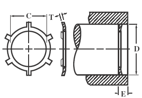
Internal Self-Locking Retaining Rings
| Housing |
Ring Dimensions |
Static Thrust Load (lb) |
|||
Min. D |
Max. D |
Thick. T |
Dia D |
Margin E |
Groove |
0.311 |
0.313 |
0.010 |
0.136 |
0.040 |
80 |
0.374 |
0.376 |
0.010 |
0.175 |
0.040 |
75 |
0.437 |
0.439 |
0.010 |
0.237 |
0.040 |
70 |
0.498 |
0.502 |
0.010 |
0.258 |
0.040 |
60 |
0.560 |
0.564 |
0.010 |
0.312 |
0.040 |
50 |
0.623 |
0.627 |
0.010 |
0.390 |
0.040 |
45 |
0.748 |
0.752 |
0.015 |
0.500 |
0.060 |
75 |
0.873 |
0.877 |
0.015 |
0.625 |
0.060 |
70 |
0.936 |
0.940 |
0.015 |
0.687 |
0.060 |
70 |
0.998 |
1.002 |
0.015 |
0.750 |
0.060 |
70 |
1.248 |
1.252 |
0.015 |
0.938 |
0.060 |
60 |
1.436 |
1.440 |
0.015 |
1.117 |
0.060 |
60 |
1.498 |
1.502 |
0.015 |
1.188 |
0.060 |
60 |
Source: Industrial Retaining Rings, 7100 Series. All dimensions are in inches. Depth of groove d = (D − G)/2. Standard material: carbon spring steel (SAE 1060-1090). Thickness indicated is for unplated rings; for plated, phosphate coated, and stainless steel rings, the maximum ring thickness may be exceeded by 0.002 inch.
Related:
- Thrust Load Capacity Retaining Rings
- Retaining Snap Ring Stress and Failure Formulas and Calculator
- Internal Retaining Snap Ring Sizes and Groove Design Chart
- Internal Retaining Snap Ring Sizes and Groove Design sizes 1.562 to 3.000
- Centrifugal Capacity Retaining Snap Rings
- Metric Tapered Retaining Snap Rings Size Chart
Link to this Webpage:
© Copyright 2000 -
2024, by Engineers Edge, LLC
www.engineersedge.com
All rights reserved
Disclaimer |
Feedback
Advertising
| Contact