Related Resources: gears
Spline Engineering Design Formula
This Spline Design Data is based on ISO 5480. ISO 5480 standard applies to splined connections with involute splines based on reference diameters for connecting hubs and shafts either with a removable connection, a sliding fit or a permanent fit. It lays down the following fundamental principles:
a) standardized uniform pressure angle of 30°,
b) the basic rack profile is the same for all pitches, therefore applying a uniform design rule to all profiles;
c) flank centring; in exceptions, diameter-centring is allowed;
d) application of profile displacements in order to achieve specific reference diameters;
e) the fit system includes tolerances for effective form deviations, meaning that the effect of such deviations on the fit backlash is taken into account; and the range of various dimension series and tolerance classes takes due consideration of all requirements.
In the formulae given in table A, the signs for the number of teeth and addendum modification factors of internal gear splines as defined in DIN 3960 have been introduced in order to facilitate the use of computers for all calculations in respect of fitted splined connections. These lead to negative signs for all hub diameters and dimensions (see DIN 3960). In the tables of dimensions given in DIN 5480-2, only the absolute values of diameters and inspection dimensions are listed, i. e. the values are to be understood as absolute values in order to avoid any misunderstanding.
Note: The module series corresponds to the module series I and II as defined in DIN 780-1 and the metric module series as defined in ISO 54:1977.
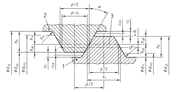
Image A
Spline Design and Engineering Formula
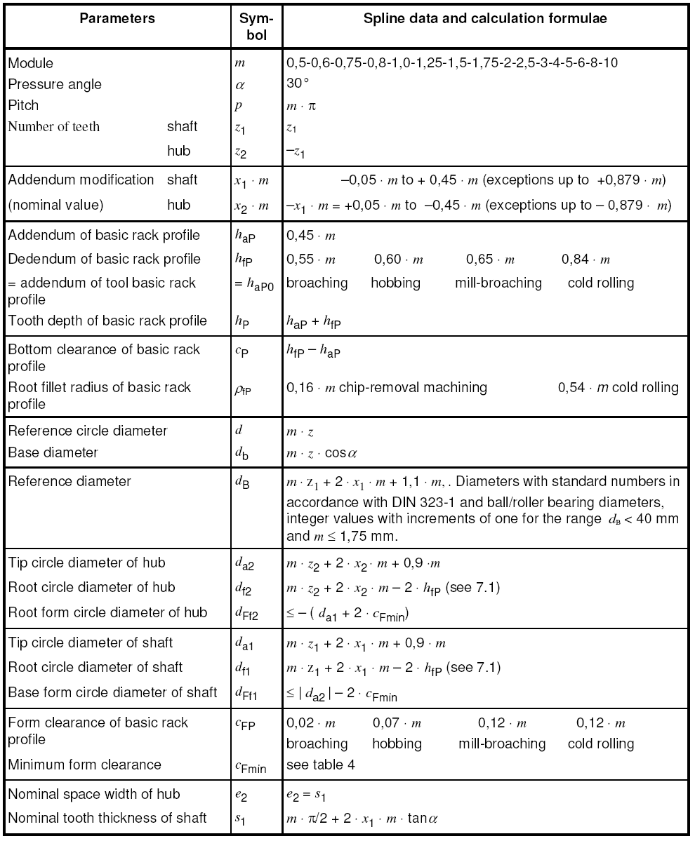
Table A
The form clearance cF is the distance between the effective root circle diameter and the root form circle diameter created by the tool. The minimum form clearance cFmin values given in table B provide an adequate excess length of the root involute so that disturbance-free contact between the involute flanks of the hub and shaft is ensured even when there are eccentricities in the motion of the interacting tip circle.
Minimum Form Design Clearance Module for Splines
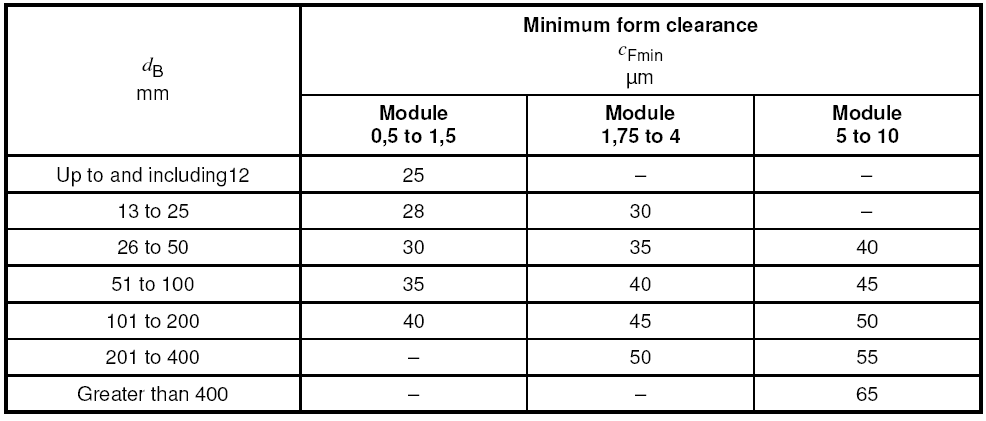
Table B
The tooth interlock of a shaft and hub splined connection is determined by the basic rack profile, the reference diameter, the module and the number of teeth. The selection of nominal dimensions is essentially determined by the following condition: the shaft cross section remaining available for transmitting torques shall not be reduced more than is necessary to permit easy slip-fitting of components such as, for instance, ball or roller bearings. In connections centred on any reference diameter, this condition is met by making the reference diameter equal to the bore of the bearing and then modifying the profiles of the teeth of the hub and the shaft accordingly.
The numbers of teeth are selected in such a way that the addendum modification necessitated by the reference diameter is kept within the range x1 × m = –0,05 × m to +0,45 × m . The mean fit angles range from 30° to more than 40°.
Link to this Webpage:
© Copyright 2000 -
2024, by Engineers Edge, LLC
www.engineersedge.com
All rights reserved
Disclaimer |
Feedback
Advertising
| Contact