Inspection Methods for Spur Gears | Single Pin Measurement Method
Gear Products and Suppliers | Gear Knowledge Menu
Inspection Knowledge Menu
There are several methods used within industry to perform dimensional conformance inspection on spur gears. In general, there are many aspects of gear inspection. This document will not attempt to address all of the variables and techniques. However, two of the most basic and important inspection criteria, are total composite error (TCE) and tooth thickness.
TCE and tooth thickness may be measured with a roll testing variable-center-distance fixture also know as "gear roll testing inspection". There are many varieties available, however basically all consist of a fixture having two parallel shafts (or precision centers), one fixed and the other floating on smooth, low-friction guide.
The gear to be inspected is mounted on one shaft while an accurate and qualified master gear is mounted on the other shaft. The pair is positioned to contact by spring loading or a similar mechanism. As the gears are rotated, tooth-to-tooth errors and runout is measured between the inspection gear and master, then these measurements are compared to acceptable dimensional limits. A great feature of gear roll testing inspection is that the inspection process is a functional inspection. When the center distance setting of the roll tester is carefully established, the tooth thickness may be derived.
There is special purpose measurement equipment available as well. The list includes involute profile form checkers, tooth-spacing gages and runout checkers. Special inspection equipment is available for inspecting high precision gears.
Other methods of inspecting spur gears are the wire or pin method. The pin (wire) methods is an accurate, easy, and useful in shops with limited inspection capabilities and equipment. Two wires or pins of known diameter are placed in diametrically opposite tooth spaces . If the gear has an odd number of teeth, the pins are located as nearly opposite as possible. The overall measurement , from the outside tangent edge of each pin is accurately measured. The measurement is then compared to calculated values based on acceptable tolerances.
Measuring Spur Gears using Single Pin Method:
There are several methods used within industry to perform dimensional conformance inspection on spur gears. In general, there are many aspects of gear inspection. This document will not attempt to address all of the variables and techniques. However, two of the most basic and important inspection criteria, are total composite error (TCE) and tooth thickness.
Equations Calculating Spur Gear Inspection Pin Diameters
Click on the image below to enlarge

Table A

Over Pins Measurement of Spur Gears
The ideal pin diameters as calculated in Table A may not be available or practical. In practice select a standard pin diameter as close to ideal value. After the actual diameter of pin dp is determined, the over pin mearsurement M can be calculated from table B.
Equation for Over Pins Measurment for Spur Gears
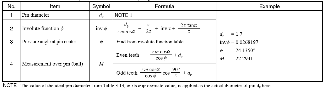
Table B
Table C - The size of the pin whic has the tangent point at d + 2xm circle or spur gears

Link to this Webpage:
© Copyright 2000 -
2024, by Engineers Edge, LLC
www.engineersedge.com
All rights reserved
Disclaimer |
Feedback
Advertising
| Contact