Related Resources: gears
Gear Design for Known Center Distance and Ratio
Gear Design for Known Center Distance and Ratio per. ANSI B6.7
Preview: Gear Design for Known Center Distance and Ratio
When it is necessary to use a pair of gears of given ratio at a specified center distance C1, it may be found that no gears of standard diametral pitch will satisfy the center distance requirement. Gears of standard diametral pitch P may need to be redesigned to operate at other than their standard pitch diameter D and standard pressure angle φ. The operating diametral pitch P1 at which these gears will operate is:
![]()
where:
Np = Number of teeth in pinion
NG = Number of teeth in gear
P1 = Operating diametral pitch (in, mm)
![]()
where:
φ1 = Operating pressure angle is
P = Diametral pitch as-built (in, mm)
P1 = Operating diametral pitch (in, mm)
Thus although the pair of gears are cut to a diametral pitch P and a pressure angle φ, they operate as standard gears of diametral pitch P1 and pressure angle φ1. The pitch P and pressure angle φ should be chosen so that φ1 lies between about 18 and 25 degrees.
The operating pitch diameters of the pinion Dp1 and of the gear DG1 are:

![]()
Base diameters of the pinion DPB1 and of the gear DGB1
![]()
![]()
Basic tooth thickness, t1, at the operating pitch diameter for both pinion and gear is:
![]()
Root diameters of the pinion DPR1 and gear DGR1
![]()
![]()
where:
![]()
![]()
bc is the hob or cutter addendum for the pinion and gear.
Tooth thicknesses of the pinion tP2 and the gear tG2 are
![]()
![]()
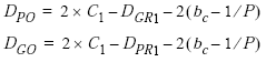
Outside diameter of the pinion DPO and the gear DGO :
Link to this Webpage:
© Copyright 2000 -
2024, by Engineers Edge, LLC
www.engineersedge.com
All rights reserved
Disclaimer |
Feedback
Advertising
| Contact