Design Equations and Formula Circular Pitches and Equivalent Diametral Pitches Table
Gear Design and Selection Application
Spur Gear Calculator and Geometry Generator - Download DXF, SVG, csv file.
Spur Gear and Assembly Builder - Download DXF, SVG ***
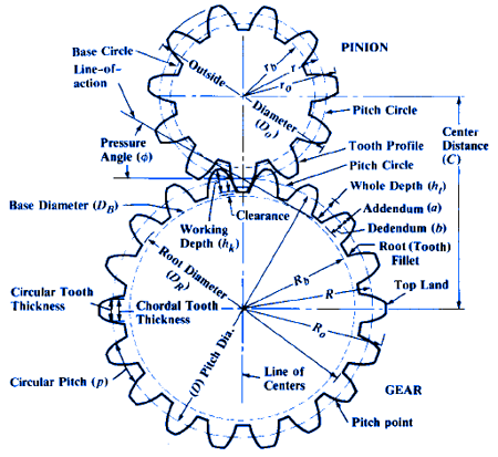
Spur Gear design formula for geometry, pitch, tooth clearance and critical functional data.
(Inch Units Applicable for Constants)
Where:
φ = Pressure Angle
a = Addendum
aG = Addendum of Gear
aP = Addendum of Pinion
b = Dedendum
c = Clearance
C = Center Distance
D = Pitch Diameter
DG = Pitch Diameter of Gear
DP = Pitch Diameter of Pinion
DB = Base Circle Diameter
DO = Outside Diameter
DR = Root Diameter
F = Face Width
hk = Working Depth of Tooth
ht = Whole Depth of Tooth
mG = Gear Ratio
N = Number of Teeth
NG = Number of Teeth in Gear
NP = Number of Teeth in Pinion
p = Circular Pitch
P=Diametral Pitch
Equations for Standards Spur Gears
| To Find | Equation | |
| Base Circle Pitch | DB = D cosφ | |
| Circular Pitch | p = ( π D )/ N |
|
| Center Distance | C = Np (mG + 1) / 2P C = ( Dp + DG ) / 2 C = ( NG + Np ) / 2P C = (NG + Np) p / 2P C = (NG + Np) p / 6.2832 |
|
| Diametral Pitch | P = π / p |
|
| Gear Ratio | mG = NG / Np | |
| Number of Teeth | N = P D N = ( π D ) / p |
|
| Outside Diameter (Full Depth Teeth) |
DO = ( N + 2 ) / P DO = [ ( N + 2 ) p ] / π |
|
| Outside Diameter (American Standard Stub Teeth) |
DO = ( N + 1.6 ) / P DO = [ ( N + 1.6 ) p ] / π |
|
| Outside Diameter | DO = D + 2a | |
| Pitch Diameter | D = N / P D = (N p ) / π |
|
| Root Diameter | DR = D - 2b | |
| Whole Depth | a + b | |
| Working Depth | aG + ap | |
Formulas for Tooth Parts, 20-and 25-degree Involute Full-depth Teeth
ANSI Coarse Pitch Spur Gear Tooth Forms ANSI B6.1
| To Calculate | Diametral Pitch, P, Known |
Circular Pitch, p, Known |
| Addendum | a = 1.000 / P |
a = 0.3183 × p |
| Dedendum (Preferred) | b = 1.250 / P |
b = 0.3979 × p |
| (Shaved or Ground Teeth)a | b = 1.350 / P |
b = 0.4297 × p |
| Working Depth | hk = 2.000 / P |
hk = 0.6366 × p |
| Whole Depth (Preferred) | ht = 2.250 / P |
ht = 0.7162 × p |
| (Shaved or Ground Teeth) | ht = 2.350 / P |
ht = 0.7480 × p |
| Clearance (Preferred)b | c = 0.250 / P |
c = 0.0796 × p |
| (Shaved or Ground Teeth) | c = 0.350 / P |
c = 0.1114 × p |
| Fillet Radius (Rack)c | rf = 0.300 / P |
rf = 0.0955 × p |
| Pitch Diameter | D = N / P |
D = 0.3183 × Np |
| Outside Diameter | DO = (N + 2) / P |
DO = 0.3183 × (N + 2) p |
| Root Diameter (Preferred) | DR = (N − 2.5) / P |
DR = 0.3183 × (N − 2.5) p |
| Root Diameter (Shaved or Ground Teeth) |
DR = (N − 2.7) / P |
DR = 0.3183 × (N − 2.7) p |
| Circular Thickness Basic | t = 1.5708 / P |
t = p / 2 |
Equations Tooth Parts, 20-and 25-degree Involute Full-depth Teeth ANSI Coarse Pitch Spur Gear Tooth Forms ANSI B6.1
a When gears are preshave cut on a gear shaper the dedendum will usually need to be increased to 1.40/P to allow for the higher fillet trochoid produced by the shaper cutter. This is of particular importance on gears of few teeth or if the gear blank configuration requires the use of a small diameter shaper cutter, in which case the dedendum may need to be increased to as much as 1.45/P. This should be avoided on highly loaded gears where the consequently reduced J factor will increase gear tooth stress excessively.
b A minimum clearance of 0.157/P may be used for the basic 20-degree and 25-degree pressure angle rack in the case of shallow root sections and use of existing hobs or cutters.
c The fillet radius of the basic rack should not exceed 0.235/P for a 20-degree pressure angle rack or 0.270/P for a 25-degree pressure angle rack for a clearance of 0.157/P. The basic rack fillet radius must be reduced for teeth with a 25-degree pressure angle having a clearance in excess of 0.250/P.
Helical Gear
Calculate |
When Defined |
Formula |
Normal D.P. (Pn) |
Transverse D.P.(P) and the Helix Angle (A) |
Pn= P / cos A |
Normal D.P. (Pn) |
Number of teeth (N) and the Helix Angle (A) |
Pn= N / (D X cos A) |
Pitch Diameter (D) |
Number of teeth (N), the Normal Diametral Pitch and the Helix Angle (A) |
D = N / (Pn X cos A) |
Outside Diameter (OD) |
Pitch Diameter (D) and the Addendum (a) |
OD = D + (2 X a) |
Outside Diameter (OD) |
Normal Diametral Pitch (P) and the Pitch Diameter (D) |
OD = D + 2/Pn |
Helix Angle (A) for Parallel Shaft Drive |
Number of Teeth (N), Pitch Diameter (D) and the Diametral Pitch (P) |
Cos A = N / (Pn X D) |
Addendum (a) |
Normal Diametral Pitch (Pn) |
a = 1 / Pn |
Lead (L) |
Pitch Diameter (D) and Pitch Helix Angle |
L = (pi*D) / Tan |
Circular Pitches and Equivalent Diametral Pitches Table
Circular Pitch |
Diametral Pitch |
Module |
Arc Thickness of Tooth on Pitch Line |
Addendum |
Working Depth of Tooth |
Dedendum or Depth of Space Below Pitch Line |
Whole Depth of Tooth |
| 4 | 0.7854 | 32.3402 | 2.0000 | 1.2732 | 2.5464 | 1.4732 | 2.7464 |
| 3 - 1/2 | 0.8976 | 28.2581 | 1.7500 | 1.1140 | 2.2281 | 1.2890 | 2.4031 |
| 3 | 1.0472 | 24.2552 | 1.5000 | 0.9549 | 1.9098 | 1.1049 | 2.0598 |
| 2 - 3/4 | 1.1424 | 22.2339 | 1.3750 | 0.8753 | 1.7506 | 1.0128 | 1.8881 |
| 2 - 1/2 | 1.2566 | 20.2117 | 1.2500 | 0.7957 | 1.5915 | 0.9207 | 1.7165 |
| 2 - 1/4 | 1.3963 | 18.1913 | 1.1250 | 0.7162 | 1.4323 | 0.8287 | 1.5448 |
| 2 | 1.5708 | 16.1701 | 1.0000 | 0.6366 | 1.2732 | 0.7366 | 1.3732 |
| 1 - 7/8 | 1.6755 | 15.1595 | 0.9375 | 0.5968 | 1.1937 | 0.6906 | 1.2874 |
| 1 - 3/4 | 1.7952 | 14.1488 | 0.8750 | 0.5570 | 1.1141 | 0.6445 | 1.2016 |
| 1 - 5/8 | 1.9333 | 13.1382 | 0.8125 | 0.5173 | 1.0345 | 0.5985 | 1.1158 |
| 1 - 1/2 | 2.0944 | 12.1276 | 0.7500 | 0.4775 | 0.9549 | 0.5525 | 1.0299 |
| 1 - 7/16 | 2.1855 | 11.6223 | 0.7187 | 0.4576 | 0.9151 | 0.5294 | 0.9870 |
| 1 - 3/8 | 2.2848 | 11.1169 | 0.6875 | 0.4377 | 0.8754 | 0.5064 | 0.9441 |
| 1 - 5/16 | 2.3936 | 10.6116 | 0.6562 | 0.4178 | 0.8356 | 0.4834 | 0.9012 |
| 1 - 1/4 | 2.5133 | 10.1062 | 0.6250 | 0.3979 | 0.7958 | 0.4604 | 0.8583 |
| 1 - 3/16 | 2.6456 | 9.6010 | 0.5937 | 0.3780 | 0.7560 | 0.4374 | 0.8154 |
| 1 - 1/8 | 2.7925 | 9.0958 | 0.5625 | 0.3581 | 0.7162 | 0.4143 | 0.7724 |
| 1 - 1/16 | 2.9568 | 8.5904 | 0.5312 | 0.3382 | 0.6764 | 0.3913 | 0.7295 |
| 1 | 3.1416 | 8.0851 | 0.5000 | 0.3183 | 0.6366 | 0.3683 | 0.6866 |
| 15/16 | 3.3510 | 7.5798 | 0.4687 | 0.2984 | 0.5968 | 0.3453 | 0.6437 |
| 7/8 | 3.5904 | 7.0744 | 0.4375 | 0.2785 | 0.5570 | 0.3223 | 0.6007 |
| 13/16 | 3.8666 | 6.5692 | 0.4062 | 0.2586 | 0.5173 | 0.2993 | 0.5579 |
| 3/4 | 4.1888 | 6.0639 | 0.3750 | 0.2387 | 0.4775 | 0.2762 | 0.5150 |
| 11/16 | 4.5696 | 5.5586 | 0.3437 | 0.2189 | 0.4377 | 0.2532 | 0.4720 |
| 2/3 | 4.7124 | 5.3903 | 0.3333 | 0.2122 | 0.4244 | 0.2455 | 0.4577 |
| 5/8 | 5.0265 | 5.0532 | 0.3125 | 0.1989 | 0.3979 | 0.2301 | 0.4291 |
| 9/16 | 5.5851 | 4.5479 | 0.2812 | 0.1790 | 0.3581 | 0.2071 | 0.3862 |
| 1/2 | 6.2832 | 4.0426 | 0.2500 | 0.1592 | 0.3183 | 0.1842 | 0.3433 |
| 7/16 | 7.1808 | 3.5373 | 0.2187 | 0.1393 | 0.2785 | 0.1611 | 0.3003 |
| 2/5 | 7.8540 | 3.2340 | 0.2000 | 0.1273 | 0.2546 | 0.1473 | 0.2746 |
| 3/8 | 8.3776 | 3.0319 | 0.1875 | 0.1194 | 0.2387 | 0.1381 | 0.2575 |
| 1/3 | 9.4248 | 2.6947 | 0.1666 | 0.1061 | 0.2122 | 0.1228 | 0.2289 |
| 5/16 | 10.0531 | 2.5266 | 0.1562 | 0.0995 | 0.1989 | 0.1151 | 0.2146 |
| 2/7 | 10.9956 | 2.3100 | 0.1429 | 0.0909 | 0.1819 | 0.1052 | 0.1962 |
| 1/4 | 12.5664 | 2.0213 | 0.1250 | 0.0796 | 0.1591 | 0.0921 | 0.1716 |
| 2/9 | 14.1372 | 1.7967 | 0.1111 | 0.0707 | 0.1415 | 0.0818 | 0.1526 |
| 1/5 | 15.7080 | 1.6170 | 0.1000 | 0.0637 | 0.1273 | 0.0737 | 0.1373 |
| 3/16 | 16.7552 | 1.5160 | 0.0937 | 0.0597 | 0.1194 | 0.0690 | 0.1287 |
| 1/6 | 18.8496 | .5053 | 0.0833 | 0.0531 | 0.1061 | 0.0614 | 0.1144 |
Resources:
- Involute Spline and Serration Universal Design Calculator
- Gear Spur Tooth Strength Equation and Calculator
- Helical Gear and Pinion Equations and Calculator
- Three Gears Ratios, Force Equations and Calculator
- Automotive Transmission Gear Ratio Equation and Calculator
- Screw Worm Gear Axial Force and Thrust Calculator
- Gear Motor Transmission Inertia Drive Calculator
Link to this Webpage:
© Copyright 2000 -
2024, by Engineers Edge, LLC
www.engineersedge.com
All rights reserved
Disclaimer |
Feedback
Advertising
| Contact