Related Resources: calculators
Stepped Labyrinth Seal Equation and Calculator
Fluids Flow Design and Engineering
Stepped Labyrinth Seal using Zimmermann and Wolff Equation and Calculator
A step can be incorporated into a labyrinth seal design to prevent carryover of kinetic energy from occurring. This provides improved sealing characteristics in comparison to straight labyrinth seals. However, radial space must be available in machines where sealing is required to accommodate a stepped seal. In addition, axial pressure gradients acting on step faces can cause undesirable axial loads. The geometric form of the seal can be defined to enhance the dissipation of kinetic energy. Such stepped seals have been applied to gas turbine engine applications.
Studies on stepped labyrinth seals have been reported by a number of researchers, including Stocker (1976), Stocker et al. (1977), Vermes (1961), Benckert and Wachter (1979), Stepanoff (1931), Isaacson (1957) and Yamada (1962); a variety of flow models have been developed for stepped labyrinth seals, as indicated in Table 1. The detailed flow structure of flow in stepped labyrinth configurations has been studied by Rhode et al. (1997a,b).
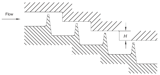
Figure 1 Stepped Labyrinth Seal
Preview Stepped Labyrinth Seal Calculator
In the absence of a validated database or code, the model proposed by Zimmermann and Wolff (1998) is suggested for stepped labyrinths, based on the following equation:
Eq. 1, mass flow
where
m = mass flow rate (kg/s)
A = annular clearance area of the seal (m2)
pt0 = upstream total pressure (Pa)
pn = downstream static pressure (Pa)
R = characteristic gas constant (J / kg-K)
Tt0 = upstream total temperature (K)
ks = correction factor for Cd
Cd = discharge coefficient
n = number of labyrinth fins (-)
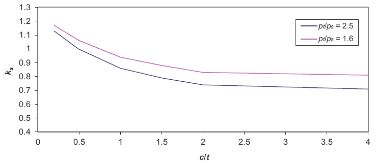
Figure 1
Cd correction factor vs c/t
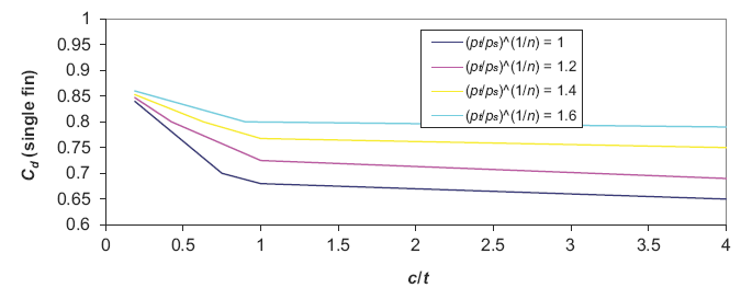
Figure 2, Discharge coefficients for a stepped labyrinth seal (single fin).
c = seal clearance (m)
t =
fin-tip land width (m)
Typical Cd ranges of values of the discharge coefficient
0.53 ≤ Cd ≤ 0.64 for c/t = 0.909
0.46 ≤ Cd ≤ 0.57 fo c/t = 1.515
0.46 ≤ Cd ≤ 0.53 for c/t = 2.424
Zimmermann and Wolff (1998) presented proprietary data for the influence of step height A minimum at H / lpitch = 0.075 is recommended if practicable.
Mechanical Design Engineering Handbook
Peter R. N. Childs
2014
Related:
- Straight Labyrinth Seal Flow Equation and Calculator
- Orifice Plate Flow Calculations and Design
- Orifice Plate Type Flow Detector Review
- Orifice Submerged in Liquid Discharge Rate Calculator and Equation
- Air Leakage Rates for Typical Home Components
- Mass Flow Rate for Gas Pipeline Blowdown through Hole or Orifice Excel Spreadsheet Calculator
- Gas Compressibility Factor (Gas Deviation Factor)
- Gas Flow Under Laminar Viscous Conditions Equations and Calculator
- Gas Material Balance Equation
- Pitot-Static Tube Velocity of Fluid Flow Measurement Calculator and Equation
- Venturi Flow Equation and Calculator
- Gas Compressibility Factor Spreadsheet Calculator
- General Energy Equation Conservation of energy principle states that energy can be neither created nor destroyed.
- Simplified Bernoulli Equation Steady flow system in which no work is done on or by the fluid, no heat is transferred to or from the fluid, and no change occurs in the internal energy
- Head The term head is used by engineers in reference to pressure.
- Energy Conversions in Fluid Systems Energy Conversions in Fluid Systems Bernoulli's Equation
- Restrictions on the Simplified Bernoulli Equation Restrictions on the Simplified Bernoulli Fluid
- Extended Bernoulli Bernoulli equation can be modified to take into account gains and losses of head.
- Application of Bernoulli's Equation to a Venturi A venturi, may be analyzed using Bernoulli's equation and the continuity equation.
- Fluid Characteristics Chart Table | Fluids Data, Fluids Density | Vapor Pressure | Kinematic Viscosity
- Fluid Characteristics Chart Table #2 | Fluids Data, Fluids Density
Link to this Webpage:
© Copyright 2000 -
2024, by Engineers Edge, LLC
www.engineersedge.com
All rights reserved
Disclaimer |
Feedback
Advertising
| Contact