Related Resources: calculators
Rotating Shaft Design Combined Loading Formulae and Calculator
Machine Design Application, Equations and Calculators
Design of Rotating Shafts under Combined Loading Calculator
ASME Design Code for the design of Transmission Shafting
Preview ASME Design Code for the design of Transmission Shafting Calculator
According to Fuchs and Stephens (1980), between 50% and 90% of all mechanical failures are fatigue failures. This challenges the engineer to consider the possibility of fatigue failure at the design stage. Figure 1 shows the characteristic variation of fatigue strength for steel with the number of stress cycles. For low strength steels, a “leveling off” occurs in the graph between 106 and 107 cycles under noncorrosive conditions and, regardless of the number of stress cycles beyond this, the component will not fail due to fatigue. The value of stress corresponding to this leveling off is called the endurance stress, or the fatigue limit.
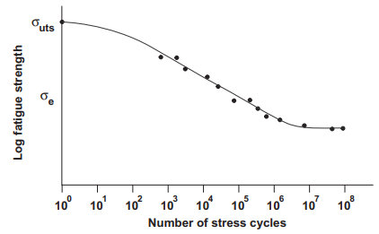
Figure 1 A typical strength cycle diagram for various steels.
In order to design hollow or solid rotating shafts under combined cyclic bending and steady torsional loading for limited life, the ASME design code for the design of transmission shafting can be used. The ASME procedure ensures that the shaft is properly sized to provide adequate service life, but the designer must ensure that the shaft is stiff enough to limit deflections of power transfer elements, such as gears, and to minimize misalignment through seals and bearings. In addition, the shaft's stiffness must be such that it avoids unwanted vibrations through the running range
The equation for determining the diameter for a solid shaft is given by
Eq. 1
where
d = diameter (m),
ns = factor of safety,
M = bending moment (N-m),
σe = endurance limit of the item (N/m2 ),
σy = yeild strength (N/m2 ),
T = torque (N-m).
There is usually some uncertainty regarding what level a component will actually be loaded to, how strong a material is, and how accurate the modeling methods are. Factors of safety are frequently used to account for these uncertainties. The value of a factor of safety is usually based on experience of what has given acceptable performance in the past. The level is also a function of the consequences of component failure and the cost of providing an increased safety factor. As a guide, typical values for the factor of safety based on strength recommended by Vidosek (1957) are as follows:
- 1.25 to 1.5 for reliable materials under controlled conditions subjected to loads and stresses known with certainty,
- 1.5 to 2.0 for well-known materials under reasonably constant environmental conditions subjected to known loads and stresses,
- 2.0 to 2.5 for average materials subjected to known loads and stresses,
- 2.5 to 3.0 for less well-known materials under average conditions of load, stress, and environment,
- 3.0 to 4.0 for untried materials under average conditions of load, stress, and environment, and
- 3.0 to 4.0 for well-known materials under uncertain conditions of load, stress, and environment.
The endurance limit, σe , for a mechanical element can be estimated ( Marin, 1962 ) by Eq. 2. Here a series of modifying factors is applied to the endurance limit of a test specimen for various effects such as size, load, and temperature.
Eq. 2
σe = kakbkc kd ke kgσ'e
where
ka = surface factor,
kb = size factor,
kc = reliability factor,
kd = temperature factor,
ke = duty cycle factor,
kf = fatigue stress concentration factor,
kg = miscellaneous effects factor, and
σ'e = endurance limit of test specimen (N/m2 ).
If the stress at the location under consideration is greater than σ'e, then the component will fail eventually due to fatigue (i.e. the component has a limited life).
Mischke (1987) has determined the following approximate relationships between the endurance limit of test specimens and the ultimate tensile strength of the material (for steels only):
σ'e = 0.504 σuts = for σuts ≤ 1400 MPA
σ'e = 700 MPa = for σuts ≥ 1400 MPA
The surface finish factor
Eq. 3
ka = aσbuts
Surface finish factors (Noll and Lipson, 1946)| Surface finish |
a (MPa) |
b |
| Ground |
1.58 |
-0.085 |
cold drawn |
4.51 |
-0.265 |
Hot rolled |
57.7 |
-0.718 |
Forged |
272.0 |
-0.995 |
reliability factor kc
| Shaft nominal reliability | kc |
| 0.5 | 1.0 |
| 0.9 0. | 897 |
| 0.99 | 0.814 |
| 0.999 | 0.753 |
For temperatures between -57 °C and 204 °C, the temperature factor, kd, can be taken as 1.0.
The ASME standard documents the values to use outside of this range.
Duty cycle factor ke is used to account for cycle loading experienced by the shaft such as stops and starts, transient overloads, shock loading, etc. and requires prototype fatigue testing for its quantification.
ke is taken 1.0 whne data is not valiable
kf is the fatigue stress concentration factor kf is used to account for stress concentration regions such as notches, holes, keyways, and shoulders.
Eq. 4
kf = 1 + q (kt - 1)
where
q = notch sensitivity
kt =
geometric stress concentration factor.
kg = miscellaneous effects factor - up to you to figure that one out, (use 1.0).
Peter R. N. Childs
2014
Related:
- The Shaft Design Book
- Shaft Reliability and Design Formulae and Calculator
- Power Transmission Shaft Design Formulas and Calculator
- Distance Between Bearings on Shaft Design Formula and Calculator
- Helix Gearing with Shafts at Any Angle Center Distance Approximate Design Equations and Calculator
- ASME Shaft Design Allowable Stress and Diameter equations and calculators
- Design of Load Carrying Shaft With One Pulley Supported by Two Bearings
- Force to Press Together Hub and Shaft Design Equations and Calculator
- Helical Gears Shafts Parallel Center Distance Approximate Design Equations and Calculator
- Gears Shafts Right Angles Exact Helix Design Equations and Calculator
- Helical Gears Shafts Right Angles Approximate Design Equations and Calculator
- Shaft Couplings Design Equation and Calculator
- Sleeve Shaft Coupling Design Equations and Calculator
- Bearing Shaft and Housing Installation Tolerances
- Shaft to Shaft Axial Alignment Tolerances
- Fatigue and Maximum Shear Stress Theory Equations and Calculator
- Solid Bolted Shaft Coupling Design Equations and Calculator
- Design Guidelines for Drive Shaft Installation Angle
- Shaft Keyway Shear and Yield Strength Formulae and Calculator
Link to this Webpage:
© Copyright 2000 -
2024, by Engineers Edge, LLC
www.engineersedge.com
All rights reserved
Disclaimer |
Feedback
Advertising
| Contact