Related Resources: calculators
Power Screw Moment and Axial Load Formulas and Calculator
Machine Design and Engineering
Power Screw Turning Moment and Axial Load Formulas and Calculator
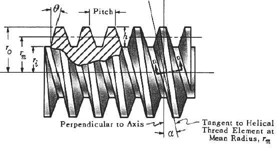
Figure 1 - Click on image to enlarge
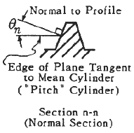
Figure 2 Power Screw Thread Section
Turning Moment and Axial Load are related to each other through the following equation for advance against load (or raising the load).
Preview Power Screw Turning Moment and Axial Load Calculator
Pitch is the distance from a point on one thread to the corresponding point on the next adjacent thread, measure parallel to the axis.
Lead is the distance the screw would advance relative to the nut in one direction. For a single thread screw, lead is equal to the pitch. For a double thread screw, lead is equal to twice the pitch, etc.
Helix angle α is related to the lead and the mean radius rm by the equation:
Equation 1
tan α = lead / ( 2 π rm )
In some calculations we shall make use of the angle θn measuring the slope of the thread profile in a normal section. This is related to the angle θ in the
Equation 2
tan αn = tan θ cos α
Note: That cos θn appears in the equations to follow, it is frequently replaced by cos θ. This yields an approximate equation that, for the usual small values of α, introduces no great error.
Power Thread Torque Eq. 3
T = W [ rm ( ( tan α + f / cos θn ) / ( 1 - f tan α / cos θn ) + fc rc ]
The torque required to advance the screw (of nut) in the direction of the load (or lowering the load) is:
Eq. 4
T = W [ rm ( ( -tan α + f / cos θn) / ( 1 - f tan α / cos θn ) + fc rc ]
This torque may be either positive or negative. If positive, work must be done to advance the screw. If negative, the meaning is that , for equilibrium, the torque must retard rotation, i.e. the axial load alone will cause rotation (the push drill situation). In this case the screw is said to be overhauling.
Where:
T = torque applied to turn screw or nut, whichever is rotated, in-lb
W = load parallel to the screw axis, lb
rm = mean thread axis (pitch diameter), in
rc = effective radius of rubbing surface which the load bears collar radius, in
f = coefficient of friction between screw and nut threads
fc - coefficient of friction at collar
α - helix angle of thread ar mean radius, degrees
θn = angle between tangent to tooth profile (on the loaded side) and a radial line, measured in plane normal to thread helix at mean radius, in
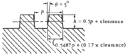
Figure 3 Modified Square Thread Form
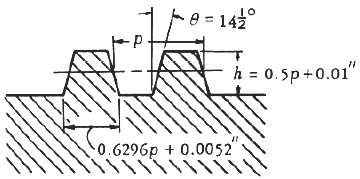
Figure 4 ACME Thread Form
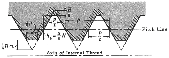
Figure 5 American Standard Thread Form - Click on image to enlarge
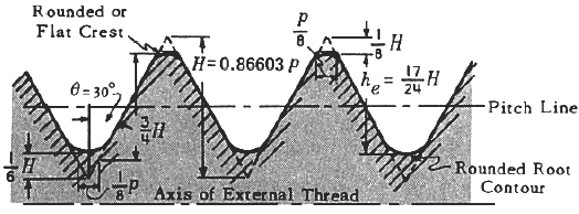
Figure 6 American Standard Thread Form - Click on image to enlarge
Related:
- Double Square-Thread Power Screw Axial Linear Lifting Force Equations and Calculator
- Power Screws Design Equation and Calculator
- Power Screw Buckling and Deflection Equations and Calculator
- Screw Worm Gear Axial Force Equation and Calculator
- Power Transmission Shaft Design Formulas and Calculator
- Cross Shaft Torsional Deflection, Stress Equation and Calculator
- Strength and Mechanics of Materials
- ASME Shaft Design Allowable Stress and Diameter equations and calculators
References:
- Schaum's Outline Theory and Problems of Machine Design -
- McGraw Hill (1968),
- Allen S. Hall, Alfred R. Holowenko,
- Herman G. Laughlin
Link to this Webpage:
© Copyright 2000 -
2024, by Engineers Edge, LLC
www.engineersedge.com
All rights reserved
Disclaimer |
Feedback
Advertising
| Contact