Related Resources: calculators
Flywheel Inertial Energy Formula and Calculator
Machine Design Engineering and Design
Inertial Energy and Angular Acceleration of a Flywheel Formula and Calculator
Flywheels store and release the energy of rotation, called inertial energy. The primary purpose of a flywheel is to regulate the speed of a machine. It does this through the amount of inertia contained in the flywheel, specifically the mass moment of inertia. Flywheels are typically mounted onto one of the axes of the machine, integral with one of the rotating shafts. Therefore, it is the mass moment of inertia about this axis that is the most important design parameter. As stated in the introduction to this chapter, too much inertia in the flywheel design and the system will be sluggish and unresponsive, too little inertia and the system will lose momentum over time.
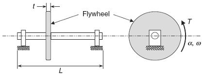
Figure 1
Solid disk flywheel integral to a rotating shaft
Preview Inertial Energy and Angular Acceleration of a Flywheel Calculator
Inertial Energy of a Flywheel Formulas:
Shown in Fig. 1 is a solid disk flywheel integral to a rotating shaft supported by appropriate bearings at each end. The applied torque (T ) produces an angular acceleration, denoted (α), which in turn produces an angular velocity, denoted by (ω).
The torque (T ) can vary over time; therefore, the angular acceleration (α) and angular velocity (ω) must also vary over time.
The relationship between the torque (T ) and the angular acceleration (α) for a flywheel and shaft assembly rotating about a fixed axis is given by Eq. 1) as
Mean spring force
Eq 1
T = Itotal α = ( I flywheel + Ishaft )
α
Eq. 1.5
α = T / ( I flywheel + Ishaft ) = T / Itotal
where (Itotal) is the total mass moment of inertia, which is the sum of the mass moment of inertia of the flywheel (I flywheel) and the mass moment of inertia of the shaft (Ishaft), both calculated about the axis of rotation.
For a solid disk flywheel with an outside radius (ro) and inside radius (ri) mounted on a shaft with an outside radius equal to the inside radius of the flywheel, the mass moments of inertia (I flywheel) and (Ishaft) are given by the following two formulas as:
Eq. 2
I flywheel = ρ π t ( ro2 - ri2 ) 2
Eq. 3
I shaft = ρ π L ri4
where (t) is the thickness of the flywheel and (L) is the length of the shaft, and where the density (ρ) of the flywheel and shaft are assumed to be the same.
The inertial energy (Einertial) of the flywheel and shaft assembly is given by the relationship:
Eq. 4
Einertial = 0.5 I total ω2
If the flywheel and shaft assembly is accelerated from one angular velocity (ω1) to another angular velocity (ω2), either speeding up or slowing down, the change in inertial energy levels is the work done on or by the system, denoted (Work 1→2), and is given by the relationship
Eq. 5
Work 1→2 = 0.5 I total ( ω21 - ω22 )
If the system is speeding up, the work done (Work 1→2 ) is positive. Conversely, if the system is slowing down, the work done (Work 1→2 ) is negative.
Converting rpm to rad/s
Eq. 6
rad / sec = rpm * (2 π /rev ) * 1 min / 60 s
Declarations:
L = length (ft, m),
ρ = density (slug/ft3, kg/m3),
ro = outside radius of flywheel (ft, m),
ri = inside radius of flywheel excluding shaft (ft, m),
t = thickness of flywheel (ft, m),
α = angular acceleration (rad/s2)
ω1, 2 = angular velocity (rad/s)
Related:
- Thin Wall Shaft Mass Moment of Inertia
- Tangent Drive Motor Mass Moment of Inertia Equation
- Estimated Motor and Transmission Inertia and Drive Requirements
- Solid Cylinder Mass Moment of Inertia Equation and Calculator
- Gear Drive Motor Mass Moment of Inertia Equation
- Direct Drive Motor - Load Mass Moment of Inertia Equation
- General Equation and Calculator Mass Moment of Inertia
Source:
Mark's Calculations for Machine Design
Thomas H. Brown, Jr.
Faculty Associate
Institute for Transportation Research and Education
NC State University
Raleigh, North Carolina
Link to this Webpage:
© Copyright 2000 -
2025, by Engineers Edge, LLC
www.engineersedge.com
All rights reserved
Disclaimer |
Feedback
Advertising
| Contact