Related Resources: calculators
Flat Thrust Plate Bearing Design Equation and Calculator
Machine Design Applications
Bearing Engineering and Design
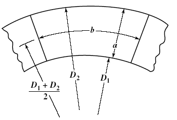
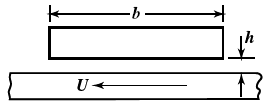
Flat Thrust Plate Bearing Design Equation and Calculator: Fluid thrust bearings contain a number of sector-shaped pads, arranged in a circle around the shaft, and which are free to pivot. These create wedge-shaped regions of oil inside the bearing between the pads and a rotating disk, which support the applied thrust and eliminate metal-on-metal contact. Although each bearing section is wedge shaped, as shown below right, for the purposes of design calculation, it is considered to be a rectangle with a length b equal to the circumferential length along the pitch line of the section being considered, and a width a equal to the difference in the external and internal radii.
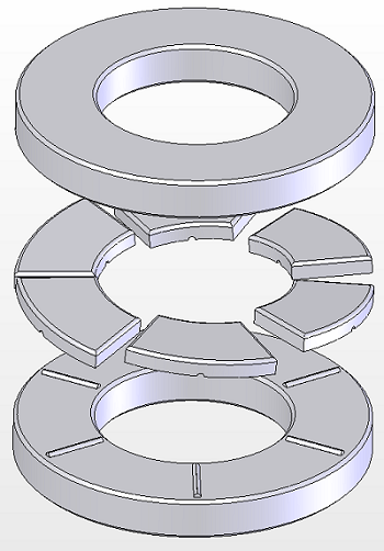
Typical Thrust Plate
Basic Element of thrust bearing
Preview: Flat Thrust Plate Bearing Design Calculator
|
Thrust Bearing Typical Loads
|
||
|
Surface
|
Loads
Lbs/in2 |
Max Loads
Lbs/in2 |
|
Parallel surface
|
< 75
|
< 150
|
|
Step Surface
|
200
|
500
|
|
Tapered Land Surface
|
200
|
500
|
|
Tilting Pad Surface
|
200
|
500
|
Reproduced with permission from Wilcock and Booser, Bearing Design and Applications, McGraw-Hill Book Co., Copyright © 1957.
External diameter formula:
D2 = ( ( 4 W ) / ( ( π Kg p ) + D12 )1/2
Where:
W = applied load, pounds
Kg = fraction of circumference occupied by pads; usually, 0.8
p = bearing unit load, psi
Radial pad width, given in inches
a = (1/2) ( D2 - D1 )
Pitch line circumference, given in inches
B = π ( D2 - a )
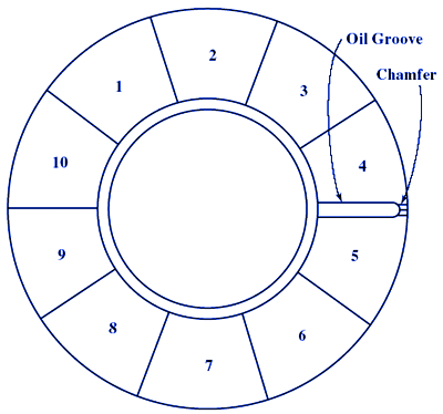
Number of bearing pads, i. Assume that the oil groove width, s is minimum
i = B / ( a + s ) = nearest even number
i as the nearest even number to that calculated.
Length of bearing pad given in inches
b = [ B - ( i s ) ] / i
Actual unit load, given in psi
p = W / ( i a b)
Pitch line velocity, given in fpm
U = ( B N ) / 12
where, N - rpm
Friction power loss, given in HP
Pf = i a b M
M = Horsepower Loss per in2 derived from:
Friction power loss, M, vs. peripheral speed, U — thrust bearings.chart
Oil flow required, given in gpm
Q = ( 42.4 Pf ) / ( c Δt )
where:
c = Specific heat of oil in Btu/gal/°F
Δt = temperature rise °F
Film flow, given in gpm
Qf = [ ( 1.5 ) ( 105 ) i V h3 ps ] / Z2
Where:
V = effective width-to-length ratio for one pad, a/b
Z2 = oil viscosity at outlet temperature
h = film thickness
Note: Because h cannot be calculated, use h = 0.002 inch.
Required flow per. chamfer, given in gpm
Qc = Q / i
Kinetic energy correction factor ξ derived from chart using values Z2l and Qc
Kinetic energy correction factor chart
Uncorrected flow per chamfer, given in gpm
Qoc = Qc / ξ
Depth of chamfer, given in inches
g = [ ( Qoc l Z2 ) / ( 4.74 x 10⁴ ps ) ]1/4
Flat plate thrust bearing example design.
Notation:
a = radial width of pad, inches
b = circumferential length of pad at pitch line, inches
b2 = pad step length
B = circumference of pitch circle, inches
c = specific heat of oil, Btu/gal/°F
D = diameter, inches
e = depth of step, inch
f = coefficient of friction
g = depth of 45° chamfer, inches
h = film thickness, inch
i = number of pads
J = power loss coefficient
K = film thickness factor
Kg = fraction of circumference occupied by the pads; usually, 0.8
l = length of chamfer, inches
M = horsepower per square inch
N = revolutions per minute
O = operating number
p = bearing unit load, psi
ps = oil-supply pressure, psi
Pf = friction horsepower
Q = total flow, gpm
Qc = required flow per chamfer, gpm
Qoc = uncorrected required flow per chamfer, gpm
QF = film flow, gpm
s = oil-groove width
∆t = temperature rise, °F
U = velocity, feet per minute
V = effective width-to-length ratio for one pad
W = applied load, pounds
Yg = oil-flow factor
Yl = leakage factor
YS = shape factor
Z = viscosity, centipoises
α = dimensionless film-thickness factor
δ = taper
ξ = kinetic energy correction factor
References:
- Machinery's Handbook, 29th Edition
- Understanding Journal Bearings, Malcolm E. Leader, P.E. Applied Machinery Dynamics Co.
- Theory and Practice of Lubrication for Engineers by Dudley D. Fuller, Wiley and Sons, 1984, ISBN 0- 471-04703-1
- Bearing Design and Application by Donald F. Wilcock and E. Richard Booser, McGraw Hill, 1957, 195, LC number 56-9641
Link to this Webpage:
© Copyright 2000 -
2024, by Engineers Edge, LLC
www.engineersedge.com
All rights reserved
Disclaimer |
Feedback
Advertising
| Contact