Related Resources: calculators
Fan And Ventilation Requirements Procedure , Equations and Calculator
Heat Transfer Design and Engineering
Industrial Electric Motors
Fan And Ventilation Requirements Procedure, Equations and Calculator.
This webpage describes basic methods of selecting typical ventilation and cooling products based on their use and provides and example calculation and calculator.
Step 1: Determine the system or devices required internal temperature. Specifications and condition.
Step 2: Determine the amount of heat energy generated internally by the device. Heat energy generated within the system or device.
Step 3: Once you have determined the amount of heat generated, the number of degrees the temperature must be lowered and what the ambient temperature should be, calculate the air flow required
Step 4: Select a fan using the required air flow. The air flow of a mounted fan can be found from the fan's air flow vs. static pressure characteristics and the pressure loss of the object to be cooled. It is difficult to calculate the device's pressure loss, so an estimation for the maximum air flow of 1.3 to 2 times the required air flow may be used.
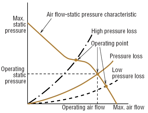
Air Flow-Static Pressure Characteristic
Calculation Example
Cabinet Specifications
| Description |
Letter
|
Specifications | |
| Installation Conditions |
-
|
Warehouse Floor | |
|
Cabinet
Enclosure |
Size |
W
H D |
Width 0.48 m (19 in.) Height 1.44 m (57 in. ) Depth 0.36 m (14 in.) |
| Surface Area |
S*
|
2.42 m2 (3758 in.2) | |
| Material |
-
|
Steel | |
| Overall Heat Transfer Coefficient |
U
|
5 W/ (m2/K) | |
| Target Temperature Rise |
ΔT
|
50°F (10°C) Ambient Temperature T1 25°C (77F°) Max. temperature inside of cabinet T2 35°C (95F°) |
|
| Total Heat Generation |
Q
|
1200 W | |
|
Factor of Safety |
Sf
|
2 | |
| Power Source |
-
|
60 Hz 115 VAC | |
Surface of Cabinet = Side Area x Top Area
Surface of Cabinet =1.8 x H x (W + D) + 1.4 x W x D
Surface of Cabinet = 2.42 m2 (3758 in.2)
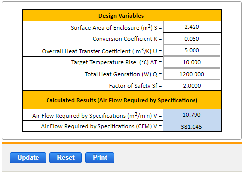
Air Flow Required by Specifications
K Conversion Coefficient = 0.05
V = K x (Q / ( ΔT) - U x S) x Sf
V = 0.05 x (1200 / (10 - 5 ) x 2.42) x 2
V = 10.8 [m3/min] ( 381 [CFM] )
Preview: Fan And Ventilation Requirements Calculator (Membership Required: Premium).
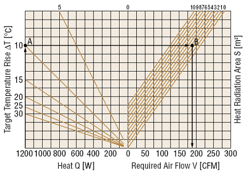
Determine Required Air Flow Using a Graph
1. Search for the cross point A between output of heat Q (1200 W) and target temperature rise ΔT [50°F (10°C)].
2. Draw a line parallel with the x axis from point A.
3. Search for the cross point B between the parallel line and surface area S [2.42 m2 (3758 in.2)] line.
4. Draw a line to the x axis from point B, required airflow is approx. 190 CFM [5.4 (m3/min)].
5. Use a safety factor of Sf = 2, Required airflow will be about 380 CFM [10.8 (m3/min)].
6. Select a fan that meets requirements as calculated.
Link to this Webpage:
© Copyright 2000 -
2024, by Engineers Edge, LLC
www.engineersedge.com
All rights reserved
Disclaimer |
Feedback
Advertising
| Contact