Related Resources: calculators
Allowable Loads and Stress in Wood Formulae and Calculator
Strength Mechanics of Materials
Beam Deflections, Stress Analysis and Engineering
Civil Engineering and Design
Bolts and Screws Design Rules for Wood Installation
Allowable Loads and Stress in Wood with Fastener
Screw Spacing in Wood
Allowable Loads and Stress in Wood with Fastener - Wood Post-1991 Equations and Calculator
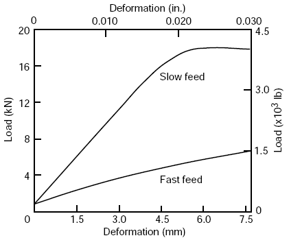
The bearing strength of wood under bolts is affected considerably by the size and type of bolt holes into which the bolts are inserted. A bolt hole that is too large causes nonuniform bearing of the bolt; if the bolt hole is too small, the wood will split when the bolt is driven. Normally, bolts should fit so that they can be inserted by tapping lightly with a wood mallet. In general, the smoother the hole, the higher the bearing values Deformations accompanying the load are also less with a smoother bolt hole surface.
 |
|
Typical load–deformation curves
showing the effect of surface condition of bolt holes, resulting from a slow feed rate and a fast feed rate, on the deformation in a joint when subjected to loading under bolts. |
Rough holes are caused by using dull bits and improper rates of feed and drill speed. A twist drill operated at a peripheral speed of approximately 38 m/min (1,500 in/min) produces uniformly smooth holes at moderate feed rates. The rate of feed depends upon the diameter of the drill and the speed of rotation but should enable the drill to cut rather than tear the wood. The drill should produce shavings, not chips. Proportional limit loads for joints with bolt holes the same diameter as the bolt will be slightly higher than for joints with a 1.6-mm (1/16-in.) oversized hole. However, if drying takes place after assembly of the joint, the proportional limit load for snug-fitting bolts will be considerably less due to the effects of shrinkage.
Screw Spacing in Wood
The center-to-center distance along the grain should be at least four times the bolt diameter for parallel-to-grain loading. The minimum center-to-center spacing of bolts in the across-the-grain direction for loads acting through metal side plates and parallel to the grain need only be sufficient to permit the tightening of the nuts. For wood side plates, the spacing is controlled by the rules applying to loads acting parallel to grain if the design load approaches the bolt bearing capacity of the side plates. When the design load is less than the bolt-bearing capacity of the side plates, the spacing may be reduced below that required to develop their maximum capacity.
When a joint is in tension, the bolt nearest the end of a timber should be at a distance from the end of at least seven times the bolt diameter for softwoods and five times for hardwoods. When the joint is in compression, the end margin may be four times the bolt diameter for both softwoods and hardwoods. Any decrease in these spacing's and margins will decrease the load in about the same ratio.
For bolts bearing parallel to the grain, the distance from the edge of a timber to the center of a bolt should be at least 1.5 times the bolt diameter. This margin, however, will usually be controlled by (a) the common practice of having an edge margin equal to one-half the distance between bolt rows and (b) the area requirements at the critical section. (The critical section is that section of the member taken at right angles to the direction of load, which gives the maximum stress in the member based on the net area remaining after reductions are made for bolt holes at that section.) For parallel-to-grain loading in softwoods, the net area remaining at the critical section should be at least 80% of the total area in bearing under all the bolts in the particular joint under consideration; in hardwoods it should be 100%.
For bolts bearing perpendicular to the grain, the margin between the edge toward which the bolt pressure is acting and the center of the bolt or bolts nearest this edge should be at least four times the bolt diameter. The margin at the opposite edge is relatively unimportant.
Allowable Loads and Stress in Wood with Fastener - Wood Pre-1991
Parallel to Grain—The starting point for parallel-to-grain bolt values is the maximum green crushing strength for the species or group of species. Procedures outlined in ASTM D2555 are used to establish a 5% exclusion value. The exclusion value is divided by a factor of 1.9 to adjust to a 10-year normal duration of load and provide a factor of safety. This value is multiplied by 1.20 to adjust to a seasoned strength. The resulting value is called the basic bolt-bearing stress parallel to grain.
The basic bolt-bearing stress is then adjusted for the effects of L/D ratio.
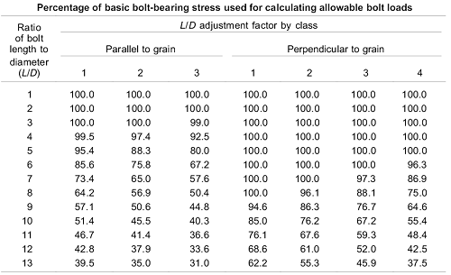
Percentage of basic stress for
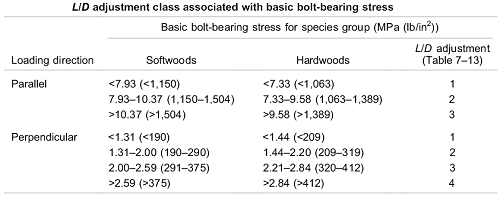
three classes of species. The particular class for the species is
determined from the basic bolt-bearing stress as indicated in
Table below.
The adjusted bearing stress is further multiplied by a factor of 0.80
to adjust to wood side plates. The allowable
bolt load in pounds is then determined by multiplying
by the projected bolt area, LD.
Perpendicular to Grain—The starting point for perpendicular-to-grain bolt values is the average green proportional limit stress in compression perpendicular to grain. Procedures in ASTM D2555 are used to establish compression perpendicular values for groups of species. The average proportional limit stress is divided by 1.5 for ring position (growth rings neither parallel nor perpendicular to load during test) and a factor of safety. This value is then multiplied by 1.20 to adjust to a seasoned strength and by 1.10 to adjust to a normal duration of load. The resulting value is called the basic bolt-bearing stress perpendicular to grain.
The basic bolt-bearing stress is then adjusted for the effects of bolt diameter. The allowable bolt load is then determined by multiplying the adjusted basic bolt-bearing stress by the projected bolt area, LD.
Allowable Loads and Stress in Wood with Fastener - Wood Post-1991 Equations and Calculator
The empirical design approach used prior to 1991 was based on a tabular value for a single bolt in a wood-to-wood, three member connection where the side members are each a minimum of one-half the thickness of the main member. The single-bolt value must then be modified for any variation from these reference conditions. The theoretical approach, after 1991, is more general and is not limited to these reference conditions.
The theoretical approach is based on work done in Europe (Johansen 1949) and is referred to as the European Yield Model (EYM). The EYM describes a number of possible yield modes that can occur in a dowel-type connection (Fig. 7–4). The yield strength of these different modes is determined from a static analysis that assumes the wood and the bolt are both perfectly plastic. The yield mode that results in the lowest yield load for a given geometry is the theoretical connection yield load.
Equations and Calculator corresponding to the yield modes for a three member joint:
Preview Dowel fastener bearing strength Calculator
Parallel to grain
Fe = 77.2G (metric SI Units),
Fe = 11,200G (inch–pound)
Perpendicular to grain
Fe = 212.0G1.45D-0.5 (metric SI Units),
Fe = 6,100G1.45D-0.5(inch–pound)
Where:
Fe = Dowel surface bearing strength (MPa, lb/in2),
G = Specific gravity based on oven dry weight and volume,
D = Bolt diameter (mm, in.).
References:
- AF&PA. 1997. National design specification for wood construction. Washington, DC: American Forest & Paper Association.
- ASCE. 1995. Standard for load and resistance factor design (LRFD) for engineered wood construction. Washington, DC:
- American Society of Civil Engineers. ASCE. 1996. Mechanical connections in wood structures. Washington, DC: American Society of Civil Engineers.
Link to this Webpage:
© Copyright 2000 -
2024, by Engineers Edge, LLC
www.engineersedge.com
All rights reserved
Disclaimer |
Feedback
Advertising
| Contact