Related Resources: belt design
Synchronous Timing Belt Pulley Table per ANSI / RMA IP-24
Belt Drive Design and Engineering
Mechanical Gear Design and Engineering
Synchronous Timing Belt Pulley and Flange Dimensions Table per ANSI / RMA IP-24, ISO 5299 and IS 9804.
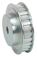
Synchronous timing gears are used with toothed timing belts to transmit rotary or linear motion. Timing gears and belts are commonly used with stepper motors for precision driven movement. The principle benefit is the ability to separate the motor and load without needing rigid complex gear trains. Timing gear-belt chains can be low-backlash, and are tolerant of shaft misalignment and mechanical imprecision.
 |
|
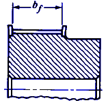 Flanged Timing Belt Pulley |
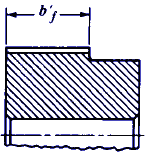 UnFlanged Timing Belt Pulley |
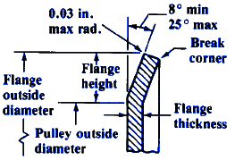 Synchronous Timing Belt Pulley Flange Dimensions |
|
All dimensions are given in inch units
|
Belt
|
Standard Nominal
Pulley Width |
Standard Pulley
Width Designation |
Minimum Pulley
Width |
Flange
|
||
|
Flanged
bf |
Unflanged
b′ f |
Thickness
(min) |
Height
(min) |
|||
|
MXL
|
0.25
|
025
|
0.28
|
0.35
|
0.023
|
0.020
|
|
XL
|
0.38
|
037
|
0.41
|
0.48
|
0.029
|
0.040
|
|
L
|
0.50
|
050
|
0.55
|
0.67
|
0.050
|
0.065
|
|
0.75
|
075
|
0.80
|
0.92
|
|||
|
1.00
|
100
|
1.05
|
1.17
|
|||
|
H
|
1.00
|
100
|
1.05
|
1.23
|
0.050
|
0.080
|
|
1.50
|
150
|
1.55
|
1.73
|
|||
|
2.00
|
200
|
2.08
|
2.26
|
|||
|
3.00
|
300
|
3.11
|
3.29
|
|||
|
XH
|
2.00
|
200
|
2.23
|
2.46
|
0.098
|
0.190
|
|
3.00
|
300
|
3.30
|
3.50
|
|||
|
4.00
|
400
|
4.36
|
4.59
|
|||
|
XXH
|
2.00
|
200
|
2.23
|
2.52
|
0.127
|
0.245
|
|
3.00
|
300
|
3.30
|
3.59
|
|||
|
4.00
|
400
|
4.36
|
4.65
|
|||
|
5.00
|
500
|
5.42
|
5.72
|
|||
References:
Machinery's Handbook, 29th Edition
ANSI / RMA IP-24
ISO 5299
S 9804
Related
- Torque Rating Synchronous Timing Belt Equation and Calculator
- Synchronous Timing Belt Pitches
- Horsepower Rating Synchronous Timing Belt Equations and Calculator
- V Belt Application and Design Considerations
- Motor Shaft Load Due to Belt Loading Equations and Calculator
- Power Transmission by Leather Belting
- V & Flat Belt Design Equations and Formulae
- Flat Belt Design Equations
- Service Factors Synchronous Timing Belts
- V Belt Rated Horsepower Equations | Design Pulley Speed Ratio |Power Calculations V-Belt | Dynamic or Two-Plane Balancing Equation
- Synchronous Timing Belt Pulley Standard Diameters
- Timing Belt Pulley Tolerances per. ANSI RMA IP-24
- Synchronous Timing Belt Standard Widths and Tolerances
- Synchronous Timing Belt Tooth Section Dimensions Table per ANSI / RMA IP-24, ISO 5299 and IS 9804
- Synchronous Timing Belt Lengths and Tolerances per. ANSI RMA IP-24, ISO 5299 and IS 9804
Link to this Webpage:
© Copyright 2000 -
2024, by Engineers Edge, LLC
www.engineersedge.com
All rights reserved
Disclaimer |
Feedback
Advertising
| Contact