Related Resources: calculators
Shaft Reliability and Design Formulae and Calculator
Shaft in Torsion Reliability and Design Formula and Calculator
A shaft is a rotating member, usually of a circular cross section, used to transmit power or motion. It provides the axis of rotation, or oscillation of other parts such as gears, flywheels and pulleys and controls the geometry of their motion. One of the functions of a shaft is transmitting torque from one element to another on the shaft. Power is transmitted by means of rotational motion and developed torque from one end of the shaft to the other. An example would be a compressor as a load driven by a motor with the compressor shaft connected to the motor shaft via a shaft coupling. Typical shaft loads include such components as fluid drivers, gears, spline's and pulleys. Reliability issues for shafts include material strength, rotational speed, shear stress, temperature, and the operating environment.
Flexible shafts provide the capability of transmitting motion around corners. A flexible shaft is made by winding several layers of wire around a central core. Flexible shafts are rated by specifying the torque corresponding to various radii of curvature of casing. A wire rope may be used as a flexible shaft.
Preview: Shaft in Torsion Design and Reliaility Calculator
Shafts are primarily designed on the basis of the torsional moment which they transmit. This torque can be calculated using the following expression:
Eq. 1
Where:
T = torque, in-lbs
hp = transmitted horsepower
N = Shaft rpm
shear stress on the shaft can be calculated from the following:
Eq. 2
$$S_s = {16 \cdot T \over \pi \cdot d^3}$$
Where:
d = shaft diameter, in
The reliability of the shaft itself is generally very high when compared to other components. Studies have shown (Reference Igor J. Karassik et al, Pump Handbook,) that the average failure rate for the shaft itself is about eight times less than mechanical seals and about three times less than that of the ball bearings. The possibility that the shaft itself will fracture, or become inoperable is very unlikely when compared to the more common component failure modes. Normally, it will be the seals or bearings of the component that will cause the initial problems. The effect of the shaft on reliability of other components is of greater importance than the reliability of the shaft itself.
The shaft reliability model is shown by the following equation:
Eq. 3
The above reliability equation for shafts assumes a constant rotational torque loading due to transmitted power and completely reversed bending loads on the shaft due to its rotation. In the case of large reciprocating loads such as those in piston engines and compressors, this assumption must be analyzed and the failure rate adjusted accordingly.
Where:
λSH = Shaft failure rate, failures/million cycles
λSH,B = Shaft base failure rate, failures/million cycles
λSH,B = 1 / Nf
Where:
Nf = Number of cycles to failure at application stress level, SED
SED = Material endurance limit, lbs/in2
The endurance limit, SED, for some common steels and alloys is shown in Table 4
Cf = is the shaft surface finish factor that adjusts the base failure rate by an amount depending on the type of manufactured finish. If the design calls for a particular finish, then a variation from this finish during the manufacturing process will alter the reliability of the shaft. See table 3.
CT = Material temperature multiplying factor
Eq. 4
CT = ( 460 + TAT ) / 620 for TAT > 160°
CT = 1.0 for for TAT ≤ 160°
Where
TAT = Operating temperature, °F
CDY = Shaft displacement multiplying factor
Eq. 5
where:
E = Modulus of elasticity of shaft material, lbs/in2
b = Specified shaft deflection, in
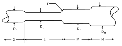
DX,L,M,N = Length of shaft section, in
Ix, L, M, N = Area moment of inertia in4
Eq. 6
Ix, L, M, N = (π µ d4 / 64 )
Figure 1 - Shaft Diameters
CSC = Stress concentration factor for shaft discontinuities, such as shoulder radii or shaft grooves etc..
Eq. 6
CSC = CSC,R + CSC,G
where
CSC,R = Stress concentration factor due to transition between
shaft sections
CSC,G = Stress concentration factor due to shaft grooves, see Table 2
CSC,R = ( 0.3 / ( r / d ) )0.2 · ( D / d ) ( 1 - ( r / d ) )
Figure 2, Typical shaft assembly
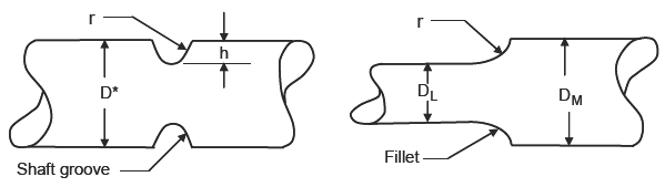
where
r = Radius of fillet, in
D = Initial shaft diameter, in
d = Transitioned shaft diameter, in
Table 2, Stress Concentration Factor CSC,G for Shaft Groves
h/D |
h/r |
||||||
0.1 |
0.5 |
1.0 |
2.0 |
4.0 |
6.0 |
8.0 |
|
0.05 |
1.10 |
1.45 |
1.60 |
2.00 |
2.05 |
- |
- |
0.10 |
1.00 |
1.27 |
1.40 |
1.70 |
2.00 |
2.225 |
- |
0.20 |
1.00 |
1.10 |
1.20 |
1.31 |
1.60 |
1.75 |
2.00 |
0.30 |
1.00 |
1.10 |
1.10 |
1.20 |
1.35 |
1.48 |
1.55 |
Table 3, Shaft Surface Finish Factor
Finish |
Cf ( Eq. 7 ) |
Polished |
1.0 |
Ground |
0.89 |
Hot Rolled |
0.94 - 0.0046 TS + 8.37 x 10⁻⁶ (TS)2 |
Machined or Cold Drawn |
1.07 - 0.005 TS + 2.21 x 10⁻⁵ (TS)2 - 3.57 x 20-8 (TS)3 |
Forged |
0.75 - 4.06 x 10⁻³ (TS)2 + 7.58 x x10-6 (TS)2 |
TS = Tensile strength of material, kpsi
Table 4, Average Values of Endurance Limits
Material |
Endurance Limit SED |
Steel, σT,ult ≤ 200 kpsi |
0.50 σT,ult |
Steel, σT,ult> 200 kpsi |
100 kpsi |
Magnesium |
0.35 σT,ult |
Nonferrous Alloy |
0.35 σT,ult |
Aluminum Alloy (wrought) |
0.40 σT,ult |
Aluminum Alloy (wrought) |
0.30 σT,ult |
Where:
σT,ult = Material ultimate tensile strength, psi
Reference:
- Hindhede, U., et al, “Machine Design Fundamentals”, John Wiley & Sons, NY, 1983
- Igor J. Karassik et al, Pump Handbook, McGraw-Hill Book Company, New York (1986).
- Shigley, J.E., Mischke, C.R. “Mechanical Engineering Design”, McGraw-Hill Book Company, NY, (1989)
- Centrifugal Pump & Mechanical Seal Manual, William J. McNally, 2009
- “Run Times”, August 2005, Dale B. Andrews, Lawrence Pumps, Inc.
- “Tidal Current Turbine Reliability: Power Take-off Train Models and Evaluation, C. Iliev and D. Val, Third International Conference on Ocean Energy, October 2010
Related
- The Shaft Design Book
- Torsional Rigidity Solid Shaft vs Hollow Shaft Formulas and Calculator
- Shaft Keyway Shear and Yield Strength Formulae and Calculator
- Solid Shaft Equivalent of Hollow Shaft Strength Formula and Calculator
- Critical Speeds of Rotating Shafts with Single Loads Equations and Calculators
- Power Transmission Shaft Design Formulas and Calculator
- Shaft to Shaft Axial Alignment Tolerances
- ASME Shaft Design Allowable Stress and Diameter equations and calculators
- Distance Between Bearings on Shaft Design Formula and Calculator
- Bearing Shaft and Housing Installation Tolerances
- Critical Speeds of Rotating Shafts with Single Loads, First Critical Speed
- Shaft Torsional Deflection and Rigidity Formulae and Calculator
- Torsional Deflection of Shaft
- Static Loading Shaft or Axle Analysis Formula and Calculator
- Shaft Key Seat Depth Control Values S and T for Shaft and Hub ANSI B17.1
- Shaft (Arbor) Keyway Dimension Size Data - ANSI/ASME B94.19-1997
- Solid Shaft with Simple Bending Diameter Equation and Calculator
- Shaft Torsion Stress Calculator and Equations
- Diameter of Solid Shaft with Torsion Equation and Calculator
Link to this Webpage:
© Copyright 2000 -
2024, by Engineers Edge, LLC
www.engineersedge.com
All rights reserved
Disclaimer |
Feedback
Advertising
| Contact