Related Resources: mechanics machines
ASME Shaft Design Allowable Stress and Diameter equations and calculators
Machine Design and Engineering
Electric Motor Design
ASME Code Shaft Allowable Stress and ASME Code Shaft Diameter equations and calculators

The objective is to calculate the shaft size having the strength and rigidity required to transmit an applied torque. The strength in torsion, of shafts made of ductile materials are usually calculated on the basis of the maximum shear theory.
ASME Code states that for shaft made of a specified ASTM steel:
Ss(allowable) = 30% of Sy but not over 18% of Sult for shafts without keyways. These values are to be reduced by 25% if the shafts have keyways.
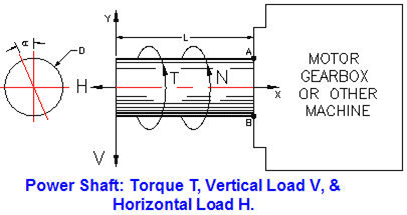
Shaft design includes the determination of shaft diameter having the strength and rigidity to transmit motor or engine power under various operating conditions. Shafts are usually round and may be solid or hollow.
Shaft torsional shear stress: Ss (lbf/in2) = T*R / J
Polar moment of area: J = π*D4 / 32 for solid shafts
J (in4) = π*(D4 - d4) / 32 for hollow shafts
Shaft bending stress: Sb (lbf/in2) = M*R / I
Moment of area: I (in4) = π*D4 / 64 for solid shafts
I (in4) = π*(D4 - d4) / 64 for hollow shafts
The ASME Code equation for shafts subjected to: torsion, bending, axial load, shock, and fatigue is:
Shaft diameter cubed,
D3 (in3) = (16/π*Ss)(1-K4))*[ ( (KbMb + (α*F α *D*(1+K2)/8 ]2 + (Kt*T)2 ]0.5
Shaft diameter cubed with no axial load,
D3 (in3) = (16/π*Ss)*[ (KbMb)2 + (Kt*T)2 ]0.5
K = D/d D = Shaft outside diameter, d = inside diameter
Kb = combined shock & fatigue bending factor
Kt = combined shock & fatigue torsion factor
All calculators require a Premium Membership