Related Resources: hardware
Slot Gages per ASME B18.2.2
Slot Gages and Gaging for Slotted Nuts per. ASME B18.2.2
The gages specified in Table calculator are used to determine the acceptability of the alignment and bottom contours of the slots in slotted nuts.
1 Diameters tabulated are equivalent to the minimum minor diameters of Class 2B threads. If the nuts are not threaded with unified coarse (UNC) or fine (UNF) threads, the diameter of gage shall be the same as the diameter of the GO thread plug gage for the bore.
The gaging for slot alignment provides for equal variations in the location of the cotter pinhole in the bolt and the location of the slots in the nut.
To inspect the nut, the slotted end of the gage shall be inserted through the threaded hole from the bearing surface of the nut. The gage pin shall then be inserted into both the gage slot and the nut slots through three adjacent faces of the nut, consecutively. Slot alignment shall be considered satisfactory if the gage pin fits into the slots without interference at all three gaging positions. The bottom contour shall be acceptable if the gage pin contacts the bottom surfaces of opposite slots during the alignment gaging at all three positions.
Some deviations from the specified gage plug diameters, D, may be necessary to compensate for variations in the nut thread minor diameter due to differences in manufacturing practices. To ensure adequate service life, gages and gage pins shall be suitably hardened.
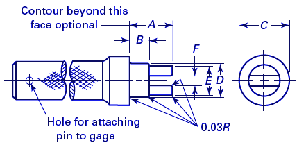
Figure 1, Slot Gage
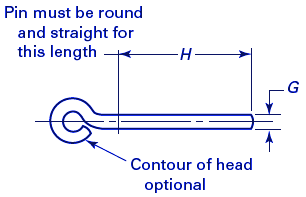
Figure 2, Gage Pin
Reference
ASME B18.2.2, Nuts for General Applications: Machine Screw Nuts, Hex, Square, Hex Flange, and Coupling Nuts (Inch Series)
Related
- Gage Design and Gage-Making Manual
- Spline Socket Go and No Go Gages
- Go and No Go Gages Hexagon Sockets
- Gage Tolerance Calculator ASME B89.1.5 Pin and Ring Gauges
- Gage Repeatability and Reproducibility Excel Spreadsheet Calculator
- Ring gage and Master Disc Tolerances per B89.1.5
- Sheet Metal Wire Gauge Sizes Data Chart | Gage Sizes Table Chart
- Go and No-Go Gage Design Calculator
- Spline Sockets Go and No Go Gages
- Gage Blocks Tolerances Specifications Table JIS B 7506
- Gage Blocks Tolerances Specifications Table BS 4311
- Thread Checking Three Wire Method
- Go and No-Go Gage Design Specification for Mechanical Inspection Calculator
- Measuring Radius of Arc With Gage Pins or Plugs Formula and Calculator
Link to this Webpage:
© Copyright 2000 -
2024, by Engineers Edge, LLC
www.engineersedge.com
All rights reserved
Disclaimer |
Feedback
Advertising
| Contact