Related Resources: bearing
Tapered Roller Bearing Setting Methods
Bearing Engineering and Applications
Tapered Roller Bearing Setting Methods and Design
Designers of gearing or wheel systems often will seek arrangements that can offer little to no movement or “play” of the components mounted on the shaft attached to the gear. Tapered roller bearings, if assembly is properly controlled, are ideally suited to these applications.
Tapered roller bearings can be set during machine assembly to any desired axial or radial clearance. This unique feature enables a designer to control bearings to meet anticipated application operating conditions, and thereby provide optimum bearing and system performance. Some advantages of tapered roller bearings pertaining to setting include:
- Longer bearing life, achieved by optimizing bearing settings while meeting application performance requirements.
- Increased mounting stiffness, achieved by properly set tapered roller bearings resulting, for example, in better gear contact and longer gear life.
- Easier assembly because cone and cup are separable.
- The bearings can be set at the time of machine assembly, allowing wider shaft and housing tolerances.
- When adjusting tapered roller bearings against each other, the bearings must be rotated so that the rollers assume their correct position, i.e. the large end face of the rollers must be in contact with the guide flange.
Bearing "Settting": With tapered roller bearings, the term “setting” simply indicates the specific amount of end play (axial clearance) or preload (axial interference) within a mounted bearing. The flexibility to easily adjust and optimize setting at the time of assembly is an inherent advantage of tapered roller bearings. Unlike other types of anti-friction bearings, tapered roller bearings do not require tight control of shaft or housing fits to obtain setting. Because tapered roller bearings are mounted in pairs (Figure 1), their setting is primarily dependent upon the axial location of one bearing row relative to the opposite row.
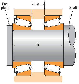
Figure 1: Simplified bearing assembly showing a typical tapered roller bearing (indirect) mounting
The three primary conditions of bearing setting are defined as:
- End play — An axial clearance between rollers and races
producing a measurable axial shaft movement when a
small axial force is applied, first in one direction and then
in the other, while oscillating or rotating the shaft (the reference bearing load zone less than 180 degrees). - Preload — An axial interference between rollers and races such that there is no discernible axial shaft movement when measured as described above. A rolling resistance to shaft rotation results which may be measured (load zone greater than 180 degrees).
- Line-to-line — A zero setting condition, the transitional point between end play and preload.
Manual Bearing Setting Considerations
Bearing setting obtained during initial assembly and adjustment is the cold or ambient bearing setting and is established before the equipment is subjected to service.
Bearing setting during operation is known as the operating bearing setting and is a result of changes in the ambient bearing setting due to thermal expansion and deflections encountered during service. The ambient bearing setting necessary to produce the optimum operating bearing setting varies with the application. Application experience, or testing, generally permits the determination of optimum settings. Frequently, however, the exact relationship of ambient to operating bearing settings is unknown and an educated estimate has to be made.
Tapered roller bearing preload, properly controlled, can actually enhance the life of the bearing system as shown on the curve. Too much preload and the life will drastically diminish and parasitic energy losses will increase. Determining the exact setting needed is the key to a high performance system where both long life for reliability, low system parasitic energy loss, and no play are required.
Generally, the ideal operating bearing setting is near- zero (axial force applied by securing nut or enmd play) to maximize bearing life. Most bearings are set with a cold setting of end play at assembly. This comes as close as possible to the desired near-zero setting when the unit reaches its stabilized operating temperature.
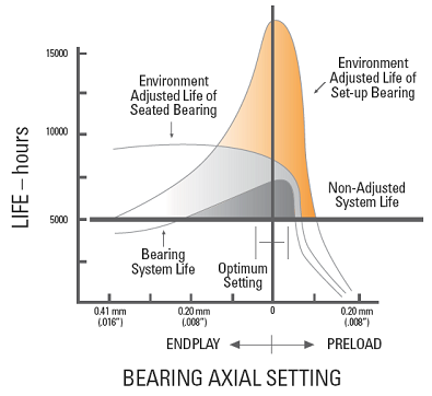
Figure 2. Calculated Bearing L10 Life vs. Operating Setting
Some applications are set with cold preload to increase rigidity and axial positioning of highly stressed parts that would otherwise be dramatically affected by excessive deflection and misalignment.
Excessive operating preload must be avoided as bearing fatigue life can be drastically reduced. Also, excessive operating preload can lead to lubrication problems and premature bearing damage due to high heat generation.
Manual Bearing Setting Methods.
Manual methods are frequently used to set bearings on a variety of equipment with low to moderate volume production requirements whereby a non- exact, primarily end play, setting range variation is acceptable. No special tooling, gauges, charts or fixtures are typically required, but assembler’s skill and judgment are necessary. For example, in the case of a conventional truck non-driven wheel with a single adjusting nut design (Figure 3), manual setting involves tightening the adjusting nut while rotating the wheel until a slight bind is felt. Then the adjusting nut is backed off 1/6 to 1/4 turn to the nearest locking hole or sufficiently to allow the wheel to rotate freely with some minimal end play. The adjusting nut is then locked in this position. Skill and judgment are required to determine when the wheel binds slightly in rotation. The more complicated the equipment and/or the larger and heavier it is, the greater degree of skill and judgment required.
Many applications utilize or require the use of two- row or close-coupled bearing assemblies. This will depend upon the design and operating characteristics of the machine (e.g. thermal growth effects, high loads, etc.). To facilitate bearing setting of this type of design, preset bearing assemblies are frequently used. Preset bearing assemblies are available in a variety of forms, styles and arrangements, but for the most part are typically referred to as spacer bearings (Figure 3). The majority of preset bearings are manufactured and supplied with spacer rings “custom fitted” between the bearing rows to control the internal clearances (ref.“2S” and “TDI” types). As such, these customized or “matched” spacers cannot be interchanged with any other bearing assembly. Other preset assemblies such as “SR” or “TNA” types may apply interchangeable spacers and/or bearing components. Such interchangeable assembly components are designed to hold closer control of the critical tolerances that affect bearing setting, and as a result, they can be randomly selected.
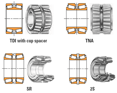
Figure 3. Example of Typical Bearing Preset Assemblies
Existing automotive or light truck applications:
For existing tapered roller bearing applications the bearing setting is determined from existing documentation, e.g. shop manual or other prepared documentation detaling the proper bearing setting. Typical these procedures specify grease requirements, bearing pre-setting torque load or torque applied to seat the bearing assembly while rotating the wheel, removal of torque then the bearing retaining nut hand tightened and then locked into place using retaining methods.
Some applications specifiy a seating torque while rotating the wheel/bearing assembly then backing off the torque a known amount of rotation (e.g. 1/4 turn). Other applications have a highly engineered hub assembly where the bearing clearance is preset and unaffected by the specified torque that is applied to secure the hub to the spindle assembly.
General taper bearing setting procedure:
- Install a castle nut (8) and tighten until the wheel (10) will not spin. this will seat the bearings into the bore.
- Loosen the castle nut (8) until the wheel (10) is free spinning.
- Tighten the castle nut (8) until the wheel (10) begins to drag.
- Align the slots in the castle nut (8) with the cross holes in the axle (9) by tightening or loosening the castle nut (8). If tightening, the wheel (10) must be able to spin somewhat freely. If loosening, the wheel (10) cannot have any end play. The bearing should have some pre-load. Install cotter pin or roll pin (4) through the slotted nut (8) and axle (9).
- Lubricate bearings through the grease zerk if provided.
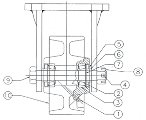
Figure 4: taper bearing setting
Reference:
Timken Company
Related:
- Tapered Land Thrust Plate Bearing Design Equation and Calculator
- Bearing Selection, Comparison and Application , Ball Bearings, Radial Bearings, Thrust Bearings, Needle Bearings Bearing Type Pure Radial Load Pure Axial load Combined Load Moment Load High Speed High Running Accuracy
- Bearing Types and Representation - Ball Bearings, Roller Bearings, Thrust Bearings, Needle Bearings Bearing Types and Representation - Ball Bearings, Roller Bearings, Thrust Bearings, Needle Bearings.
- Ball Bearings ABEC Tolerances The ABEC scale is an industry accepted standard for the tolerances of a ball bearing. It was developed by the Annular Bearing Engineering Committee (ABEC) of the American Bearing Manufacturers Association (ABMA)
Link to this Webpage:
© Copyright 2000 -
2024, by Engineers Edge, LLC
www.engineersedge.com
All rights reserved
Disclaimer |
Feedback
Advertising
| Contact