Related Resources: calculators
Tapered Land Thrust Bearing Design Equation and Calculator
Machine Design Applications
Bearing Engineering and Design
Tapered Land Thrust Plate Bearing Design Equation and Calculator:
Related:
Tapered Thrust Plate Bearing
Preview: Tapered Land Thrust Plate Bearing Design Calculator
|
Thrust Bearing Typical Loads
|
||
|
Surface
|
Loads
Lbs/in2 |
Max Loads
Lbs/in2 |
|
Parallel surface
|
< 75
|
< 150
|
|
Step Surface
|
200
|
500
|
|
Tapered Land Surface
|
200
|
500
|
|
Tilting Pad Surface
|
200
|
500
|
Reproduced with permission from Wilcock and Booser, Bearing Design and Applications, McGraw-Hill Book Co., Copyright © 1957.
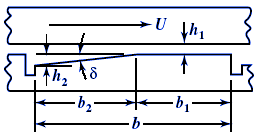
General Design Parameters: Usually, the taper extends to only 80 per cent of the pad length with the remainder being flat, thus: b2 = 0.8b and b1 = 0.2b.
External diameter formula:
D2 = ( ( 4 W ) / ( ( π Kg Pa ) + D12 )1/2
Where:
W = applied load, pounds
Kg = fraction of circumference occupied by pads; usually, 0.8
Pa = bearing unit load, psi
Radial pad width , given in inches
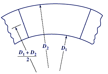
a = (1/2) ( D2 - D1 )
Pitch line circumference , given in inches
B = π (D1 - D2 ) / 2
Number of bearing pads, assume oil groove s.
i = B / ( a + s ) = nearest even number
i as the nearest even number to that calculated.
Length of bearing pad given in inches
b = ( B - i s ) / i
Taper values, δ1 and δ2 derived from Taper Table T
|
Pad Size
(inches) |
Taper
(inch) |
|
|
a x b
|
δ1 = h2 − h1
(at ID) |
δ2 = h2 − h1
(at OD) |
|
0.5 x 0.5
|
0.0025
|
0.0015
|
|
1.0 x 1.0
|
0.005
|
0.003
|
|
3.0 x 3.0
|
0.007
|
0.004
|
|
7 x 7
|
0.009
|
0.006
|
Table T
Bearing unit load, actual given in psi
p = W / ( i a b )
Pitch line velocity, given in fpm
U = ( B N ) / 12
where, N - rpm
Oil leakage factor
YL = b / [ 1 + ( π2 b2 / ( 12 a 2 ) ) ]
or can be estimated from:
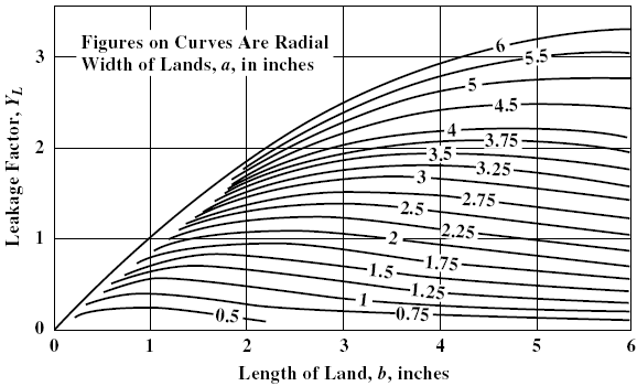
Oil leakage factor table
Film thickness factor
K = ( 5.75 x 10⁶ p ) / ( U YL Z )
Minimum film thickness given in mils inches - h should be 0.001 inch for small bearings and 0.002 inch for larger and high-speed bearings.
Use K value and the selected taper values δ1 and δ2, h is found
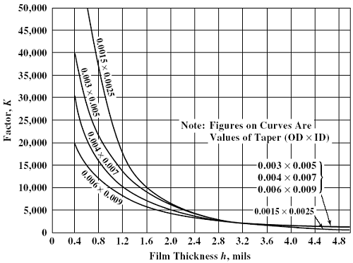
Chart h
Friction power loss (HP), derived from table using film thickness h
Pf = 8.79 x 10⁻¹³ i a b J U2 Z
coefficient J can be obtained from the following table.
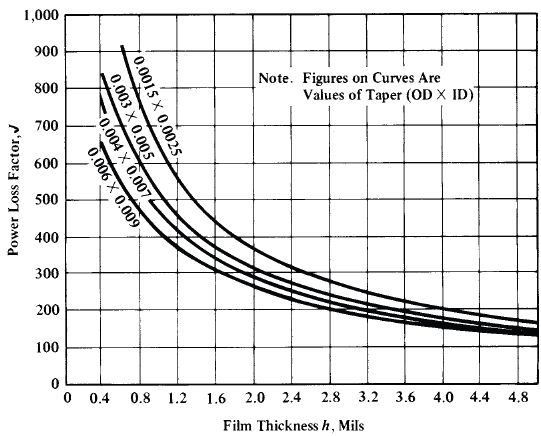
Chart J
Required oil flow, given in gpm at temperature rise Δt
Q = ( 42.4 Pf ) / ( c Δt )
Where:
c = specific heat of oil in Btu/gal/°F
Δt = 50 °F typical maximum
Shape factor
Ys = ( 8 a b ) / ( D22 - D21 )
YG Oil flow factor using Ys and D1 / D2
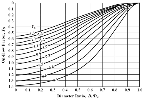
Table YG
Oil flow factor , YG vs diameter ratio D1/D2
Actual oil film flow
Qf = ( 8.9 x 10⁻⁴ i δ2 D32 N Yg Y2s ) / ( D2 - D1 )
Notation:
a = radial width of pad, inches
b = circumferential length of pad at pitch line, inches
b2 = pad step length
B = circumference of pitch circle, inches
c = specific heat of oil, Btu/gal/°F
D = diameter, inches
e = depth of step, inch
f = coefficient of friction
g = depth of 45° chamfer, inches
h = film thickness, inch
i = number of pads
J = power loss coefficient
K = film thickness factor
Kg = fraction of circumference occupied by the pads; usually, 0.8
l = length of chamfer, inches
M = horsepower per square inch
N = revolutions per minute
O = operating number
p = bearing unit load, psi
ps = oil-supply pressure, psi
Pf = friction horsepower
Q = total flow, gpm
Qc = required flow per chamfer, gpm
Qoc = uncorrected required flow per chamfer, gpm
QF = film flow, gpm
s = oil-groove width
∆t = temperature rise, °F
U = velocity, feet per minute
V = effective width-to-length ratio for one pad
W = applied load, pounds
Yg = oil-flow factor
Yl = leakage factor
YS = shape factor
Z = viscosity, centipoises
α = dimensionless film-thickness factor
δ = taper
ξ = kinetic energy correction factor
References:
- Machinery's Handbook, 29th Edition
- Understanding Journal Bearings, Malcolm E. Leader, P.E. Applied Machinery Dynamics Co.
- Theory and Practice of Lubrication for Engineers by Dudley D. Fuller, Wiley and Sons, 1984, ISBN 0- 471-04703-1
- Bearing Design and Application by Donald F. Wilcock and E. Richard Booser, McGraw Hill, 1957, 195, LC number 56-9641
Link to this Webpage:
© Copyright 2000 -
2024, by Engineers Edge, LLC
www.engineersedge.com
All rights reserved
Disclaimer |
Feedback
Advertising
| Contact