Related Resources: mechanical-tolerances
Forgings Tolerance Calculator per. EN-10243-1 Normal tolerances
Tolerances, Engineering Design & Limits & Fits
Design for Manufacturability and Assembly Resources
Steel Die Forgings Normal Tolerance and Dimensions Calculator Non-Circular Applications
Drop and vertical press forgings per. EN-10243-1 Forging grade F Tolerances for length, width, height. Type F forging tolerances are for normal or typical applications.
Information required in determining forging tolerances
To determine the tolerances applicable to a given forging the following information is required in addition to the dimensions of the forging:
- mass of forging;
- shape of die line;
- category of steel used;
- shape complexity factor;
- type of dimension.
Preview: Steel Die Forgings Tolerance and Dimensions Calculator
The shape complexity factor takes account of the fact that in forging thin sections and branched components, as compared to components having simple compact shapes, larger dimensional variations occur which are attributable to different rates of shrinkage, higher shaping forces and higher rates of die wear.
Eq. 1
Shape complexity factor
S = mf / mes
Eq. 2
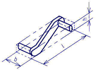
Volume of enveloping shape
v = l · b · h
Eq. 3
Non-Circular forging enveloping shape
mes = l · b · h · p
where
mf = mass forging
mes = Mass enveloping shape See figures 1 and 2
ρ = density (steel ~ 0.00785 g/mm3);
h = enveloping length;
l = enveloping length dimension;
b = enveloping width dimension;
h = enveloping height dimension
v = volume of enveloping shape
Enveloping shapes of non-circular forgings
Figure 1
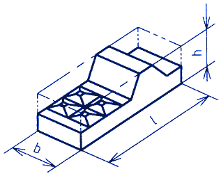
Figure 2
The resulting shape complexity factor is determined as falling within one of the following categories:
S4: Up to and including 0,16;
S3: Above 0,16 up to and including 0,32;
S2: Above 0,32 up to and including 0,63;
S1: Above 0,63 up to and including 1.
Category of steel used
The type of steel symbol used takes account of the fact that steels of high carbon and high alloy content are more difficult to deform and cause higher die wear than do steels with lower carbon content and lower alloying elements.
The category of steel used is determined as being within one of the following:
- Group M1: Steel with carbon content not more than 0,65 % and total of specified alloying elements (Mn, Ni, Cr, Mo, V, W) not more than 5 % by mass;
- Group M2: Steel with carbon content above 0,65 % or total of specified alloying elements (Mn, Ni, Cr, Mo, V, W) above 5 % by mass.
To determine the category in which a steel belongs, the maximum permitted content of the elements in the steel specification shall be the values used.
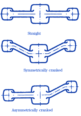
Shape of die line
Figure 3 Shape of Die
Reference:
EN 10243-1 Steel die forgings Tolerances on dimensions, Part 1: Drop and vertical press forgings
Alternatively: BS EN 10243-1, Steel die forgings Tolerances on dimensions, Part 1: Drop and vertical press forgings
Related
- Forgings Close Tolerance and Dimensions Calculator
- Forgings Tolerances for fillet , edge radii, burrs and sheared ends
- Forging Tolerances Straightness Flatness and Center-to-Center
- Standard Tolerances for Drop Forgings
- Forging Manufacturing Definitions and Terms
- Forging Manufacturing and Design | Forging Die Mechanical Tolerances
- Design For Forging Manufacturing Considerations
- ASTM A694 Forging
- BS 4620 Hot Forged Snap Head Rivet
Link to this Webpage:
© Copyright 2000 -
2024, by Engineers Edge, LLC
www.engineersedge.com
All rights reserved
Disclaimer |
Feedback
Advertising
| Contact