Related Resources: hardware
Standard Hex Lag Screws
Hardware ANSI ISO Screws and Bolts
ISO Metric Hardware Engineering Data
Standard Inch Size Hex Lag Screws per. ANSI/ASME B18.2.1
Detail dimensional data for Lag Screws
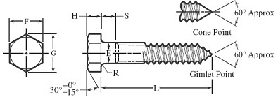
All dimensions in inches.
BOLTS AND NUTS 1594
Minimum thread length is 1⁄2 length of screw plus 0.50 inch, or 6.00 inches, whichever is shorter. Screws too short for the formula thread length shall be threaded as close to the head as practicable.
Thread formulas:
Pitch = 1 ÷ thds. per inch.
Flat at root = 0.4305 × pitch.
Depth of single thread = 0.385 × pitch.
Nominal Size |
Thds/Inch |
Thread Dimensions |
||||
Pitch P |
Flat at Root B |
Depth of Thd. T |
Root Dia. D1 |
|||
# 10 |
0.1900 |
11 |
0.091 |
0.039 |
0.035 |
0.120 |
1⁄4 |
0.2500 |
10 |
0.100 |
0.043 |
0.039 |
0.173 |
5⁄16 |
0.3125 |
9 |
0.111 |
0.048 |
0.043 |
0.227 |
3⁄8 |
0.3750 |
7 |
0.143 |
0.062 |
0.055 |
0.265 |
7⁄16 |
0.4375 |
7 |
0.143 |
0.062 |
0.055 |
0.328 |
1⁄2 |
0.5000 |
6 |
0.167 |
0.072 |
0.064 |
0.371 |
5⁄8 |
0.6250 |
5 |
0.200 |
0.086 |
0.077 |
0.471 |
3⁄4 |
0.7500 |
41⁄2 |
0.222 |
0.096 |
0.085 |
0.579 |
7⁄8 |
0.8750 |
4 |
0.250 |
0.108 |
0.096 |
0.683 |
1 |
1.0000 |
31⁄2 |
0.286 |
0.123 |
0.110 |
0.780 |
11⁄8 |
1.1250 |
31⁄4 |
0.308 |
0.133 |
0.119 |
0.887 |
11⁄4 |
1.2500 |
31⁄4 |
0.308 |
0.133 |
0.119 |
1.012 |
Nominal Size |
Body or Shoulder Dia. E |
Width Across Flats F |
Width Across Corners G |
Height H |
Shoulder Length S |
Radius Fillet R |
|||||||
Max. |
Min. |
Basic |
Max. |
Min. |
Max. |
Min. |
Basic |
Max. |
Min. |
Min. |
Max. |
||
# 10 |
0.1900 |
0.199 |
0.178 |
9⁄32 |
0.281 |
0.271 |
0.323 |
0.309 |
1⁄8 |
0.140 |
0.110 |
0.094 |
0.03 |
1⁄4 |
0.2500 |
0.260 |
0.237 |
3⁄8 |
0.438 |
0.425 |
0.505 |
0.484 |
11⁄64 |
0.188 |
0.150 |
0.094 |
0.03 |
5⁄16 |
0.3125 |
0.324 |
0.298 |
1⁄2 |
0.500 |
0.484 |
0.577 |
0.552 |
7⁄32 |
0.235 |
0.195 |
0.125 |
0.03 |
3⁄8 |
0.3750 |
0.388 |
0.360 |
9⁄16 |
0.562 |
0.544 |
0.650 |
0.620 |
1⁄4 |
0.268 |
0.226 |
0.125 |
0.03 |
7⁄16 |
0.4375 |
0.452 |
0.421 |
5⁄8 |
0.625 |
0.603 |
0.722 |
0.687 |
19⁄64 |
0.316 |
0.272 |
0.156 |
0.03 |
1⁄2 |
0.5000 |
0.515 |
0.482 |
3⁄4 |
0.750 |
0.725 |
0.866 |
0.826 |
11⁄32 |
0.364 |
0.302 |
0.156 |
0.03 |
5⁄8 |
0.6250 |
0.642 |
0.605 |
15⁄16 |
0.938 |
0.906 |
1.083 |
1.033 |
27⁄64 |
0.444 |
0.378 |
0.312 |
0.06 |
3⁄4 |
0.7500 |
0.768 |
0.729 |
11⁄8 |
1.125 |
1.088 |
1.299 |
1.240 |
1⁄2 |
0.524 |
0.455 |
0.375 |
0.06 |
7⁄8 |
0.8750 |
0.895 |
0.852 |
15⁄16 |
1.312 |
1.269 |
1.516 |
1.447 |
37⁄64 |
0.604 |
0.531 |
0.375 |
0.06 |
1 |
1.0000 |
1.022 |
0.976 |
11⁄2 |
1.500 |
1.450 |
1.732 |
1.653 |
43⁄64 |
0.700 |
0.591 |
0.625 |
0.09 |
11⁄8 |
1.1250 |
1.149 |
1.098 |
111⁄16 |
1.688 |
1.631 |
1.949 |
1.859 |
3⁄4 |
0.780 |
0.658 |
0.625 |
0.09 |
11⁄4 |
1.2500 |
1.277 |
1.223 |
17⁄8 |
1.875 |
1.812 |
2.165 |
2.066 |
27⁄32 |
0.876 |
0.749 |
0.625 |
0.09 |
Pilot Hole for Lag Screws
Pilot hole size can range as follows:
- Soft Wood 40% to 70% of the shank diameter for wood with G ≤ 0.5.
- Medium Wood 60% to 75% of the shank diameter for wood with 0.5 < G ≤ 0.6.
- Hard Wood 65% to 85% of the shank diameter for wood with a specific gravity (G) > 0.6.
Typical Pilot Hole (Drill Bit) Sizes for selected Lag Screw Diameters
| LAG SIZE |
SOFT WOOD |
MEDIUM WOOD |
HARD WOOD |
| Groups III & IV |
Group II |
Group I |
|
| 1/4” |
3/32” |
5/32” |
3/16” |
| 5/16” |
9/64” |
3/16” |
13/64” |
| 3/8” |
11/64” |
15/64” |
1/4” |
| 1/2” |
15/64” |
5/16” |
11/32” |
| 5/8” |
5/16” |
13/32” |
29/64” |
| 3/4” |
13/32” |
1/2” |
9/16” |
Source:
- Fastener and Screw / Bolt Design, Formula & Calculations
- Lag Screws in Wood Pullout Resistance Force Formulae and Calculator
- Lag Screw Withdrawal Force Formulae and Calculator
- Self Tapping Screw Pull-Out and Torque Calculator
- Pilot Holes for American Wood Screws
- American Wood Screws
- Self Tapping Screw Pull-Out and Torque Calculator
- Commercial Lumber Sizes Chart Table
- Specific Gravity and Weight of Wood
Link to this Webpage:
© Copyright 2000 -
2024, by Engineers Edge, LLC
www.engineersedge.com
All rights reserved
Disclaimer |
Feedback
Advertising
| Contact