Related Resources: calculators
Proportional Weirs Equations and Calculator
Civil Engineering and Design
Fluids Engineering and Design
Proportional Weirs Equations and Calculator
The proportional weir (Sutro weir) is used in water level control because it demonstrates a linear relationship between Q and H. Figure 1 illustrates a proportional weir whose sides are hyperbolic in shape.
Preview: Proportional Weirs Calculator
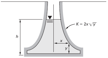
Figure 1 Proportional Weirs
aEq.1
Q = Cd · K · (π / 2) · ( 2 · g )0.5 · h
aEq. 2
K = 2 · x · y0.5
Where:
- x = on half base width in ft (m for S.I. units)
- y = height at some elevation in ft (m for S.I. units)
- Cd = discharge coefficient, average value .63
- h = base height in ft (m for S.I. units)
- K = height or curved portion of weir in ft (m for S.I. units)
- Q = design flow over the weir in cfs (m3/s for S.I. units)
- g = acceleration of gravity = 32.17 ft/s/s (9.81 m/s/s for S.I. units)
Equations Sutro Weir Design Formulas
bEq. 3
Hb = 1.5 Hc * ( Qmin / Qmax ) / ( 1 - Qmin /Qmax)
bEq. 4
Wb = Qmin / [ (2/3) 4.96 Hb1.5 ]
bEq. 5
x = ( Wb / 2 ) [ 1 - (0.315 tan-1 ( Z / Hb0.5) ) ]
X and Z are position parameters as shown in the diagram above. They will have the same units as Wb .
Where:
- Wb = base width in ft (m for S.I. units)
- Hb = base height in ft (m for S.I. units)
- Hc = max height or curved portion of weir in ft (m for S.I. units)
- Qmax = design maximum flow over the weir in cfs (m3/s for S.I. units)
- Qmin = design minimum flow over the weir in cfs (m3/s for S.I. units)
- g = acceleration of gravity = 32.17 ft/s/s (9.81 m/s/s for S.I. units)
Reference
aCivil Engineering Reference Manual, Fifteenth Edition, Michael R. Lindeburg, PE
b U.S. DOT, Fed Highway Admin, Urban Design Manual, Circular No. 22, 2nd Ed. 2001 (Publ. No. FHWA-NHI-010021-HEC-22)
bBengtson, Harlan H. , “ Proportional Weir Design Equations ,” an online blog article
Related
- Weir Flow Rectangular Open Channel Water Flow Calculator and Formula
- Trapezoidal Weirs Flow Formula and Calculator
- Triangular Weirs Flow Formula and Calculator
- Water Flow Kinetic Force in Flow Around Submerged Object Calculator and Equation.
- Dam's Spillway (overflow spillway) Flow Formula and Calculator
- Flow Through a Sluice Gate Formula and Calculator
- Flow over Channel Rise Hump Formula
- Weir Flow Rectangular Open Channel Water Flow Calculator and Formula
- Pipe Flow with Gradual Size Enlargement Formula and Calculator
- Fluid Characteristics Chart Table | Fluids Data, Fluids Density | Vapor Pressure | Kinematic Viscosity
- Fluid Characteristics Chart Table #2 | Fluids Data, Fluids Density
Link to this Webpage:
© Copyright 2000 -
2024, by Engineers Edge, LLC
www.engineersedge.com
All rights reserved
Disclaimer |
Feedback
Advertising
| Contact