Related Resources: calculators
Floating Bearing Shaft Length Design and Calculator
Bearing Application, Specifications and Engineering
Floating Bearing Shaft Length Design and Calculator
The practical use of rolling element bearings requires consideration of their installation, as well as correct selection. Bearing installation considerations include the bearing combination, the mounting of the bearings, shaft length increase in length due to temperature changes, and the provision of lubrication.
Preview Change of Shaft Length Design and Calculator
A typical application of rolling element bearings is the support of a rotating shaft. If the operating temperature of the machine varies, the shaft length can grow relative to the casing or mounting arrangement. An idea of the magnitude of the axial shaft growth can be estimated by
Eq. 1
ΔL = Lo · α · ΔT
where
ΔL = change in length (m),
Lo = original length (m),
α = coefficient of linear thermal expansion (per °C), an
ΔT = temperature rise (°C).
For a gas turbine engine the difference in temperature between the casing and the shaft can be 50 °C. If the original length of the steel shaft was 1.0 m the growth of the shaft would be
ΔL = Lo · α · ΔT
ΔL = 1.0 x 11 x 10-6 x 50
ΔL = 5.5 x 10⁻⁴
ΔL = 0.55 mm
This is a considerable axial movement within a machine and must be allowed for if significant loadings and resultant stresses and possible contact between stationary and rotating components are to be avoided. A typical solution to this kind of situation is to allow for a limited axial movement on one bearing as shown in Figure 1 and 2.
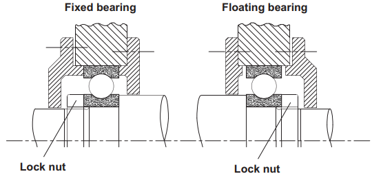
Figure 1 Basic bearing mounting using two deep groove ball bearings for a rotating horizontal shaft for moderate radial and axial loading.
Here the right-hand bearing is a cylindrical roller bearing, and the axial location of the roller is not fixed and can move or float axially to the limited extents of the race to take up any axial movement or expansion of the shaft.
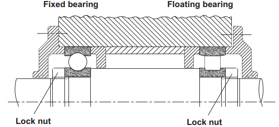
Figure 2
Basic bearing mounting using a deep groove and a cylindrical roller bearing for moderate radial loads at the “locating deep groove bearing” and high radial load capacity at the cylindrical roller bearing.
Source
Mechanical Design Engineering Handbook
Peter R. N. Childs
2014
Related:
- Nonuniform Diameter Change of Length Under Axial Force Formula and Calculator
- Linear Thermal Expansion Equation and Calculator
- Conductive Heat Transfer Eccentric Cylinder Equation and Calculator Conductive Heat Transfer of Eccentric circular isothermal cylinder of length L in a cylinder of the same length (L > D2).
- Steady State Conduction Multi layer Cylinder Calculation Equation and calculator temperature on one side of an isothermal constant temperature multilayer cylinder.
- Linear Thermal Expansion Equation and Calculator Linear expansion is the change in length as opposed to change in volume. To a first approximation, the change in length measurements of an object due to thermal expansion is related to temperature change by a "linear expansion coefficient".
- Heat Loss from a Pipe Equation and calculator will determine the heat loss through a bare pipe
- Coefficients Linear Thermal Expansion
- Overall Heat Transfer Coefficient Overall Heat Transfer Coefficient Equation
- Ball Bearings Fatigue Life Calculations and Load Ratings Fatigue life calculations assume the dispersion in life of identical ball bearings operating under identical conditions, a statistical result is obtained for bearing fatigue life.
- Bearing Shaft and Housing Installation Tolerances Size and fit tolerances for bearing mating shafts and housing are provided within the tables below are defined by ISO tolerances for shafts and housings (ISO 286) in conjunction with the tolerances Δdmp for the bore and ΔDmp for the outside diameter of the bearings per. (DIN 620)
- Bearing Design for Life and Selection Calculator
- Bearing Load Calculator Excel Spreadsheet Design engineering spreadsheet calculates the loads on linear motion bearings. *Premium Membership Required*
- Critical Speeds of Rotating Shafts with Distributed Loads Critical Speeds of Rotating Shafts with Distributed Loads - First Critical Speed
Link to this Webpage:
© Copyright 2000 -
2024, by Engineers Edge, LLC
www.engineersedge.com
All rights reserved
Disclaimer |
Feedback
Advertising
| Contact