Related Resources: pressure-vessel
Stress in Pressure Vessel Flanged or Dished Head Section Seam Equation and Calculator
Structural Design and Analysis
Pressure Vessel Design and Engineering
Stress in Pressure Vessel Flanged or Dished Head Section Seam Equation and Calculator
The stress in the girth seam will govern only when the circumferential join efficiency is less than one - half the longitudinal joint efficiency, or when the internal pressure additional loadings (wind load, reaction of saddles) are causing longitudinal bending or tension . The reason for it is that the stress arising in the girth seam pound per square inch is one - half of the stress in the longitudinal seam.
ALL calculators require a Premium Membership
Preview
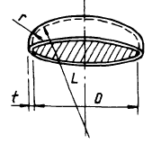
Stress in Pressure Vessel Flanged or Dished Head Section Seam Calculator:
When L/r = 16.667
Required minimum wall thickness
t = ( 0.885 P L ) / ( S E - 0.1 P)
Maximum allowable working pressure
P = ( S E ta ) / ( 0.885 L + 0.1 ta )
When L/r < 16.667
Required minimum wall thickness
t = ( P L M ) / ( 2 S E - 0.2 P )
Maximum allowable working pressure
P = ( 2 S E ta ) / ( L M + 0.2 ta )
Where:
P = Design pressure or max. allowable working pressure, psi
S = Rated stress value of the material
E = Weld Joint efficiency
R = Inside radius, inches
D = Inside diameter of vessel , inches
t = Thickness of shell (wall), inches
ta = Wall thickness used in actual design, inches
CA = Corrosion allowance, inches
Values of Factor "M" based on L/r:
|
L/r
|
1.00
|
1.25
|
1.50
|
1.75
|
2.00
|
2.25
|
2.50
|
2.75
|
3.00
|
3.50
|
3.25
|
4.00
|
4.50
|
5.00
|
5.50
|
6.00
|
6.50
|
|
M
|
1.00
|
1.03
|
1.06
|
1.08
|
1.10
|
1.13
|
1.15
|
1.17
|
1.18
|
1.20
|
1.22
|
1.25
|
1.28
|
1.31
|
1.34
|
1.36
|
1.39
|
|
L/r
|
7.00
|
7.50
|
8.00
|
8.50
|
9.00
|
9.50
|
10.0
|
10.5
|
11.0
|
11.5
|
12.0
|
13.0
|
14.0
|
15.0
|
16.0
|
16.66
|
*
|
|
M
|
1.41
|
1.44
|
1.46
|
1.48
|
1.50
|
1.52
|
1.54
|
1.56
|
1.58
|
1.60
|
1.62
|
1.65
|
1.69
|
1.72
|
1.75
|
1.77
|
-
|
* The maximum allowed ratio: L = D +2t
Link to this Webpage:
© Copyright 2000 -
2024, by Engineers Edge, LLC
www.engineersedge.com
All rights reserved
Disclaimer |
Feedback
Advertising
| Contact