Related Resources: power transmission
Roller Chain Dimensions Table per. ASME/ANSI B29.1M
Mechanical Components | Engineering Hardware
Roller Chain Dimensions per. ASME/ANSI B29.1M

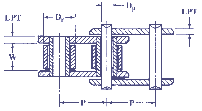
- All dimensions are in inches.
- Roller Diameters Dr are approximately 5⁄8 P.
- The width W is defined as the distance between the link plates. It is approximately 5⁄8 of the chain
pitch. - Pin Diameters Dp are approximately 5⁄16 P or 1⁄2 of the roller diameter.
- Thickness LPT of Inside and Outside Link Plates for the standard series is approximately 1⁄8 P.
- Thickness of Link Plates for the heavy series of any pitch is approximately that of the next larger
- pitch Standard Series chain.
- Maximum Height of Roller Link Plates = 0.95 P.
- Maximum Height of Pin Link Plates = 0.82 P.
- Maximum Pin Diameter = nominal pin diameter + 0.0005 inch.
- Minimum Hole in Bushing = nominal pin diameter + 0.0015 inch.
- Maximum Width of Roller Link = nominal width of chain + (2.12 × nominal link plate thickness.)
- Minimum Distance between Pin Link Plates = maximum width of roller link + 0.002 inch.
| Pitch
P |
Max.
Roller Diameter Dr |
Standard Chain
No. |
Width
W |
Standard Chain Series
|
Heavy Series
|
||
| Pin Diameter
Dp |
Thickness of
Link Plates LPT |
Measuring Load,
† Lb. |
Thickness of
Link Plates LPT |
||||
| 0.250
|
0.130 a
|
25
|
0.125
|
0.0905
|
0.030
|
18
|
…
|
|---|---|---|---|---|---|---|---|
|
0.375
|
0.200 a
|
35
|
0.188
|
0.141
|
0.050
|
18
|
…
|
|
0.500
|
0.306
|
41
|
0.250
|
0.141
|
0.050
|
18
|
…
|
|
0.500
|
0.312
|
40
|
0.312
|
0.156
|
0.060
|
31
|
…
|
|
0.625
|
0.400
|
50
|
0.375
|
0.200
|
0.080
|
49
|
…
|
|
0.750
|
0.469
|
60
|
0.500
|
0.234
|
0.094
|
70
|
0.125
|
|
1.000
|
0.625
|
80
|
0.625
|
0.312
|
0.125
|
125
|
0.156
|
|
1.250
|
0.750
|
100
|
0.750
|
0.375
|
0.156
|
195
|
0.187
|
|
1.500
|
0.875
|
120
|
1.000
|
0.437
|
0.187
|
281
|
0.219
|
|
1.750
|
1.000
|
140
|
1.000
|
0.500
|
0.219
|
383
|
0.250
|
|
2.000
|
1.125
|
160
|
1.250
|
0.562
|
0.250
|
500
|
0.281
|
|
2.250
|
1.406
|
180
|
1.406
|
0.687
|
0.281
|
633
|
0.312
|
|
2.500
|
1.562
|
200
|
1.500
|
0.781
|
0.312
|
781
|
0.375
|
|
3.000
|
1.875
|
240
|
1.875
|
0.937
|
0.375
|
1000
|
0.500
|
a Bushing diameter. This size chain has no rollers.