Related Resources: motors
Metric Stepper Motor Shafts Size Data Table
Power Transmission
Electric Motors and Driver Review
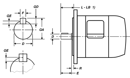
Table of dimensions for shafts, keys and keyways for metric dimension Stepper motors
Note: This document annotates dimensional data specified by NEMA standard (see bottom of webpage). Many industry stepping motor manufacturers have chosen to deviate from this industry standard.
Legend
1) L minus LB (L-LB) is the preferred designation for the length of the shaft from the mounting surface of the flange. Dimension L-LB can be determined from dimension E+R included in the tables (L-LB = E+R).
Stepper Motor shafts, keys and keyways dimensions for metric size table.
|
D
|
E
Nom. mm |
R
mm |
Key
|
Keyway
|
Max.
Cont. Shaft Torque N-m |
||||||||||||
|
F
|
GD
|
F
|
GE
|
||||||||||||||
|
Nom.
mm |
Tolb
|
Nom.
mm |
Tol.
|
Nom.
mm |
Tol.
|
Nom.
mm |
Tol.
|
Nom.
mm |
Tol.
|
||||||||
|
µm
|
µm
|
µm
|
µm
|
µm
|
µm
|
µm
|
µm
|
µm
|
µm
|
||||||||
|
5
|
+0
|
-8
|
16
|
0
|
a
|
||||||||||||
|
6
|
+0
|
-8
|
16
|
0
|
|||||||||||||
|
7
|
0
|
-9
|
16
|
0
|
2
|
0
|
-25
|
2
|
0
|
-25
|
2
|
-4
|
-29
|
1.2
|
100
|
0
|
0.25
|
|
8
|
0
|
-9
|
18
|
0
|
2
|
0
|
-25
|
2
|
0
|
-25
|
2
|
-4
|
-29
|
1.2
|
100
|
0
|
0.4
|
|
9
|
0
|
-9
|
20
|
0
|
3
|
0
|
-25
|
3
|
0
|
-25
|
3
|
-4
|
-29
|
1.8
|
100
|
0
|
0.63
|
|
10
|
0
|
-9
|
20
|
12
|
3
|
0
|
-25
|
3
|
0
|
-25
|
3
|
-4
|
-29
|
1.8
|
100
|
0
|
0.875
|
|
11
|
0
|
-11
|
23
|
0
|
4
|
0
|
-30
|
4
|
0
|
-30
|
4
|
0
|
-30
|
2.5
|
100
|
0
|
1.25
|
|
14
|
0
|
-11
|
30
|
0
|
5
|
0
|
-30
|
5
|
0
|
-30
|
5
|
0
|
-30
|
3
|
100
|
0
|
2.8
|
|
16
|
0
|
-11
|
40
|
0
|
5
|
0
|
-30
|
5
|
0
|
-30
|
5
|
0
|
-30
|
3
|
100
|
0
|
4.1
|
|
18
|
0
|
-11
|
40
|
0
|
6
|
0
|
-30
|
6
|
0
|
-30
|
6
|
0
|
-30
|
3.5
|
100
|
0
|
7.1
|
|
19
|
0
|
-13
|
40
|
0
|
6
|
0
|
-30
|
6
|
0
|
-30
|
6
|
0
|
-30
|
3.5
|
100
|
0
|
8.25
|
|
22
|
0
|
-13
|
50
|
0
|
6
|
0
|
-30
|
6
|
0
|
-30
|
6
|
0
|
-30
|
3.5
|
100
|
0
|
14
|
|
24
|
0
|
-13
|
50
|
0
|
8
|
0
|
-36
|
7
|
0
|
-90
|
8
|
0
|
-36
|
4
|
200
|
0
|
18
|
|
28
|
0
|
-13
|
60
|
0
|
8
|
0
|
-36
|
7
|
0
|
-90
|
8
|
0
|
-36
|
4
|
200
|
0
|
31.5
|
|
32
|
0
|
-16
|
80
|
0
|
10
|
0
|
-36
|
8
|
0
|
-90
|
10
|
0
|
-36
|
5
|
200
|
0
|
50
|
|
35
|
0
|
-16
|
76
|
3
|
10
|
0
|
-36
|
8
|
0
|
-90
|
10
|
0
|
-36
|
5
|
300
|
0
|
69
|
|
38
|
0
|
-16
|
80
|
0
|
10
|
0
|
-36
|
8
|
0
|
-90
|
10
|
0
|
-36
|
5
|
200
|
0
|
90
|
|
42
|
0
|
-16
|
110
|
0
|
12
|
0
|
-43
|
8
|
0
|
-90
|
12
|
0
|
-43
|
5
|
200
|
0
|
125
|
|
48
|
0
|
-16
|
110
|
0
|
14
|
0
|
-43
|
9
|
0
|
-90
|
14
|
0
|
-43
|
5.5
|
200
|
0
|
200
|
|
55
|
0
|
-41
|
110
|
0
|
16
|
0
|
-43
|
10
|
0
|
-90
|
16
|
0
|
-43
|
6
|
200
|
0
|
355
|
|
60
|
0
|
-41
|
140
|
0
|
18
|
0
|
-43
|
11
|
0
|
-110
|
18
|
0
|
-43
|
7
|
200
|
0
|
450
|
|
65
|
0
|
-41
|
140
|
0
|
18
|
0
|
-43
|
11
|
0
|
-110
|
18
|
0
|
-43
|
7
|
200
|
0
|
630
|
|
70
|
0
|
-41
|
140
|
0
|
20
|
0
|
-52
|
12
|
0
|
-110
|
20
|
0
|
-52
|
7.5
|
200
|
0
|
800
|
|
75
|
0
|
-41
|
140
|
0
|
20
|
0
|
-52
|
12
|
0
|
-110
|
20
|
0
|
-52
|
7.5
|
200
|
0
|
1000
|
|
80
|
0
|
-41
|
170
|
0
|
22
|
0
|
-52
|
14
|
0
|
-110
|
22
|
0
|
-52
|
9
|
200
|
0
|
1250
|
|
85
|
0
|
-48
|
170
|
0
|
22
|
0
|
-52
|
14
|
0
|
-110
|
22
|
0
|
-52
|
9
|
200
|
0
|
1600
|
|
90
|
0
|
-48
|
170
|
0
|
25
|
0
|
-52
|
14
|
0
|
-110
|
25
|
0
|
-52
|
9
|
200
|
0
|
1900
|
a The key and keyway is not provided for shaft numbers 5 and 6.
b Tolerances follow North American practice; alternate tolerancing is provided in IEC 60072-1.
Reference: NEMA ICS 16 Standard
Link to this Webpage:
© Copyright 2000 -
2024, by Engineers Edge, LLC
www.engineersedge.com
All rights reserved
Disclaimer |
Feedback
Advertising
| Contact