Generators Operational Characteristics Review
Industrial Electric Motors and Generators Menu
Electric Generators Suppliers
Generators operational characteristics are well understood. The following are the principle operational considerations:
Voltage - Generated voltage is the emf denoting the electric pressure between phases in the armature. The magnetic flux linking each armature coil changes as the machine rotates. The change in flux per turn occurs at the conductors in the armature slots. Each conductor is regarded separately as it cuts the flux. At a specific rotating speed, instantaneous volts per conductor are proportional to air gap flux density at the conductor.
Current - Current is the rate of transfer (flow) of electricity, expressed in amperes. Field current required for a particular load condition, i s determined by the magnetic circuit, in conjunction with armature and field windings. Load current is equal to the generated voltage divided by the impedance of the load.
Speed - Normally, a generator operates at a constant speed corresponding to the frequency and number of poles. Variations may occur due to changes in driving torque, load, field excitation, or terminal voltage.
Frequency - AC frequency is determined by the rotating speed and number of poles of the generator. Frequency is usually expressed in Hertz, the frequency used most is 60 Hertz. A two-pole generator must operate at 3600 rpm to maintain 60 Hertz. Four-pole and six-pole units must operate at 1800 rpm and 1200 rpm, respectively, to maintain 60 Hertz. Frequency at 60 Hertz is expressed in the following equation:
Frequency (60 Hertz) = (Speed in rpm)(Pair of Poles)/60
Power - power is the term used to describe the rate at which electric energy is delivered by a generator and it is usually expressed in watts or kilowatts (103 watts).
Watts - Watts are units of active or working power, computed as follows: volts x measured or apparent amperes x power factor.
Volt amperes reactance (Vars). Vars are units of reactive or nonworking power (1 var = 1 reactive volt-ampere).
Power factor - power factor is the ratio of active or working power divided by apparent power. The relationship of apparent power, active power, and reactive power is shown in below. The hypotenuse represents apparent power, the base represents active power, and the altitude power triangle represents reactive power. of the Power factor (the cosine of angle 0) is a unitless number which can be expressed in per unit or in percentage. For convenience, kilo (103) is often used with the terms volt- amperes, watts and vars in order to reduce the number of significant digits.
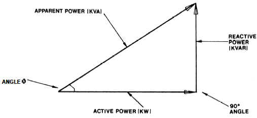
% Power Factor = kW/kVA * 100
Where:
kW = Kilo Watts
kVA = Kil0 Volt-Amps
References: “Joint Departments of the Army and the Navy, Operation Maintenance and Repair of Auxiliary Generators, 26 August 1996”
Link to this Webpage:
© Copyright 2000 -
2024, by Engineers Edge, LLC
www.engineersedge.com
All rights reserved
Disclaimer |
Feedback
Advertising
| Contact