Related Resources: mechanics machines
Flywheel and Shaft Torque Analysis
Engineering Analysis
Gear Engineering and Design
Machine Design, Equation and Calculators
Flywheel and Shaft Torque Analysis
A flywheel mounted on a relatively stiff shaft is shown in Fig. a. Considering the equilibrium of torques,
![]() eq1
eq1
where,
Ti = driving or input torque (N-m)
To = load or output torque (N-m)
I = mass moment of inertia of flywheel (kg-m2)
ω = angular velocity of shaft (rad/s) (dθ/dt)
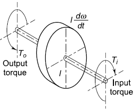
Fig. 1
Torque on Flywheel Shaft
When the driving torque is more than the load torque, the term (Ti - To) is positive and the flywheel is accelerated. When the driving torque is less than the load torque, the term (Ti - To) is negative indicating retardation of flywheel. A T -θ diagram for a particular application is shown in Fig. 2(a). In this case, the power is supplied to the machine by a constant-torque motor, developing a torque Tm. The work cycle of the driven machine consists of three parts—AB, BC and CD. During the elements AB and CD, the torque required by the machine remains constant at T1. At the point B, it increases to T2 and remains constant during the element BC. The cycle is repeated for each revolution.
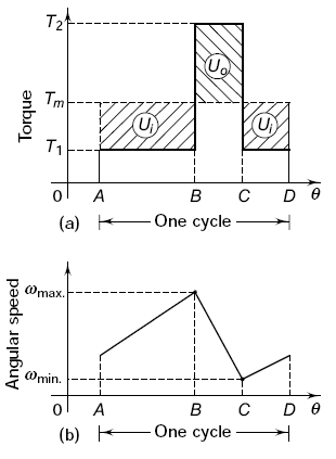
Fig. 2
(a) Torque Diagram, (b) Speed Diagram
During the first element AB, the torque required by the machine is less than that supplied by the motor (T1 < Tm). The flywheel is, therefore, accelerated and its angular velocity increases to wmax. at the point B. During the element BC, the torque required by the machine is more than the torque supplied by the motor (T2 > Tm). The flywheel is retarded and its angular velocity decreases to wmin. at point C. This variation in angular velocity is shown in Fig. 2(b).
During elements AB and CD, the energy is supplied to the flywheel. The input energy Ui is given by,
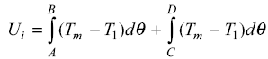 eq 2
eq 2
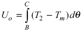
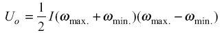
During the element BC, the energy is taken from the flywheel and the energy output Uo from the flywheel is given by,
 eq 3
eq 3
The change in kinetic energy from point B to C is given by
![]() eq 4
eq 4
or
 eq 5
eq 5
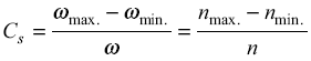
The difference between the maximum and minimum speeds (ωmax. – wmin.) during a cycle is called the maximum fl uctuation of speed. The ratio of maximum fl uctuation of speed to the mean speed is called coefficient of fluctuation of speed. Therefore, the coefficient of fluctuation of speed, denoted by Cs is given by,
![]() eq 6
eq 6
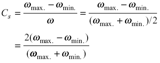
where ω is the average or mean angular velocity of the flywheel. It is given by,
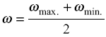 eq 7
eq 7
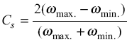
Substituting Eqs (6) and (7) in expression (a),
![]()
The values of the coefficients of fluctuation of speed, used in practice are given in Table 1. The coefficient of fluctuation of speed can be expressed in the following ways:
or
Similarly,
or
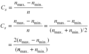
or
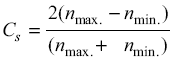
where n is the speed in rpm.
Sometimes, a term called coefficient of ‘steadiness’ is used. The coefficient of steadiness is defined as the reciprocal of the coefficient of fluctuation of speed. It is denoted by the letter m.
Therefore,
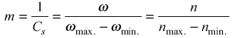
Table 1, Coefficients of Fluctuations of Speed
| Type of Equipment | Cs |
| Punching, shearing and forming presses | 0.200 |
| Compressor (belt driven) | 0.120 |
| Compressor (gear driven) | 0.020 |
| Machine tools | 0.025 |
| Reciprocating pumps | 0.040 |
| Geared drives | 0.020 |
| Internal combustion engines | 0.030 |
| D.C. generators (direct drive) | 0.010 |
| A.C. generator (direct drive) | 0.005 |
Link to this Webpage:
© Copyright 2000 -
2024, by Engineers Edge, LLC
www.engineersedge.com
All rights reserved
Disclaimer |
Feedback
Advertising
| Contact