Related Resources: material science
Pressure Vessel External Pressure Calculations
External Pressure Vessel Calculations and Design General
|
General configuration and |
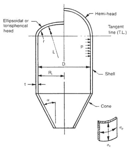
Unlike vessels which are designed for internal pressure alone, there is no single formula, or unique design, which fits the external pressure condition. Instead, there is a range of options available to the designer which can satisfy the solution of the design. The thickness of the cylinder is only one part of the design. Other factors which affect the design are the length of cylinder and the use, size, and spacing of stiffening rings. Design is an iterative procedure. First, a design is selected with all of the variables included, then the design is checked to determine if it is adequate. If inadequate, the procedure is repeated until an acceptable design is reached.
Vessels subject to external pressure may fail at well below the yield strength of the material.the critical factor rather than material strength. Failures can occur suddenly, by collapse of the component.
External pressure can be caused in pressure vessels by a variety of conditions and circumstances. The design pressure may be less than atmospheric pressure due to condensing gas or steam. Often refineries and chemical plants design all of their vessels for some amount of external pressure, regardless of the intended service, to allow forr steam cleaning and the effects of the condensing steam. Other vessels are in vacuum service by nature of venturi devices or connection to a vacuum pump. Vacuums can be pulled inadvertently by failure to vent a vessel during draining, or from improperly sized vents.
External pressure can also be created when vessels are jacketed or when components are within multi chambered vessels. Often these conditions can be many times greater than atmospheric pressure.
When vessels are designed for both internal and external pressure, it is common practice to first determine the shell thickness required for the internal pressure condition, then check that thickness for the maximum allowable external pressure. If the design is not adequate then a decision is made to either bump up the shell thickness to the next thickness of plate available, or add stiffening rings to reduce the “L’ dimension. If the option of adding stiffening rings is selected, then the spacing can be determined to suit the vessel configuration.
When neither increasing the shell thickness to remove stiffening rings or using the thinnest shell with the maximum number of stiffeners is economical. The optimum solution lies somewhere between these two extremes. Typically, the utilization of rings with a spacing of 2D for vessel diameters up to about eight feet in diameter and a ring spacing of approximately “D” for diameters greater than eight feet, provides an economical solution.
The design of the stiffeners themselves is also a trial and error procedure. The first trial will be quite close if the old APT-ASME formula is used. The formula is its follows:
Stiffeners should never be located over circurnferentlal weld seams. If properly spaced they may also double as insulation support rings. Vacuum stiffeners, if coinbined with other stiffening rings, such as cone reinforcement rings orsaddle stiffeners on horizontal vessels, must be designed for the combined condition, not each independently. If at possible, stiffeners should always clear shell nozzles. If unavoidable, special attention should be given to the design of a boxed stiffener or connection to the nozzle neck.
A =factor “A,” strain, from ASME Section TI, Part D D, Subpart 3, dimensionless
As = cross-sectional area of stiffener, in.2
R = factor “B,” allowable compressive stress, from ASME Section II, Part D, Subpart 3, psi
D = inside diameter of cylinder, in.
Do =outside diameter of cylinder, in.
DL, = outside diameter of the large end of cone, in.
Ds = outside diameter of small end of cone, in.
E = modulus of elasticity, psi
I = actual moment of inertia of stiffener, in.
Is = required moment of inertia of stiffener, in.4
Io = required moment of inertia of combined shellring cross section, in.
L = for cylinders-the design length for external pressure, including k the depth of heads, in. For cones-the design length for external pressure (see Figures 2-lb and 2-lc), in.
ASME Section 11, Part D, Subpart 3, psi
Le = equivalent length of conical section, in.
Ls = length between stiffeners, in.
LT - T = length of straight portion of shell, tangent to
tangent, in.
P = design internal pressure, psi
Pa = allowable external pressure, psi
Ps = design external pressure, psi
Rs = outside radius of spheres and hemispheres,
t =thickness of cylinder, head or conical section, in. crown radius of torispherical heads, in.
to =equivalent thickness of cone, in.
Step 1: Assume a thichess if one is not already determined.
Step 2: Calculate dimensions “L’ and “D.” Dimension “L’ should include one-third the depth of the heads. The overall length of cylinder would be as follows for the various head types:
| W/(2) hemi-heads | L = LT-T + 0.333D |
| W/(2) 2:1 S.E. heads | L = LT-T + 0.1666D |
| W/(2) 100% - 6% heads | L = LT-T + 0.112D |
Step 3: Calculate L/Do, and Do/t ratios
Step 4: Determine Factor “A’ from ASME Code, Section 11, Part D, Subpart 3, Fig G: Geometric Chart for Components Under External or Compressive Loadings (see Required Shell Thickness Cylindrical Chart #1 or Required Shell Thickness Cylindrical Chart #2)..
Step 5: Using Factor “A’ determined in step 4, enter the applicable material chart from ASME Code, Section 11, Part D, Subpart 3 at the appropriate temperature and determine Factor “B.”
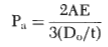
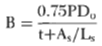
Step 6: If Factor “A’ falls to the left of the material line, then utilize the following equation to determine the allowable external pressure:
Step 7: For values of “A’ falling on the material line of the applicable material chart, the allowable external pressure should be computed as follows:

Step 8: If the computed allowable external pressure is less than the design external pressure, then a decision must be made on how to proceed. Either (a) select a new thickness and start the procedure from the beginning or (b) elect to use stiffening rings to reduce the “L’ hmension. If stiffening rings are to be utilized, then proceed with the following steps.
Step 9: Select a stiffener spacing based on the maximum length of unstiffened shell (see Required Shell Thickness Cylindrical Chart #1 or Required Shell Thickness Cylindrical Chart #2). The stiffener spacing can vary up to the maximum value allowable for the assumed thickness. Determine the number of stiffen-ers necessary and the correspondmg “L’dimension.
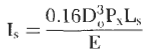
Step 10: Assume an approximate ring size based on the following equation:
image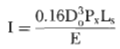
Step 11: Compute Factor “B” from the following equation utilizing the area of the ring selected
Step 12: Utilizing Factor “B” computed in step 11, find the corresponding “A’ Factor from the applicable material curve.
Step 13:Determine the required moment of inertia from the following equation. Note that Factor “A” is the one found in step 12.
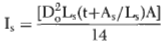
Step 14: Compare the required moment of inertia, I, with the actual moment of inertia of the selected member. If the actual exceeds that which is required, the design is acceptable but may not be optimum. The optimization process is an iterative process in which a new member is selected, and steps 11 through 13 are repeated until the required size and actual size are approximately equal.
Notes:
1. For conical sections where alpha < 22.5 degrees, design the cone as a cylinder where Do=DL and length is equal to L.
2. If a vessel is designed for less than 15psi, and the external pressure condition is not going to be stamped on the nameplate, the vessel does not have to be designed for the external pressure condition.
Link to this Webpage:
© Copyright 2000 -
2024, by Engineers Edge, LLC
www.engineersedge.com
All rights reserved
Disclaimer |
Feedback
Advertising
| Contact