Related Resources: material science
Measuring Case Depth Hardness
Engineering Applications and Design
Engineering Materials
Methods of Measuring Case Depth Hardness
Case hardening may be defined as a process for hardening a ferrous material in such a manner that the surface layer, known as the case, is substantially harder than the remaining material, known as the core. The process embraces carburizing, nitriding, carbonitriding, cyaniding, induction, and fíame hardening. In every instance, chemical composition, mechanical properties, or both are affected by such practice.
This testing procedure describes various methods for measuring the depth to which change has been made in either chemical composition or mechanical properties. Each procedure has its own area of application established through proved practice, and no single method is advocated for all purposes.
Methods employed for determining the depth of case are either chemical, mechanical, or visual, and the specimens or parts may be subjected to the described test either in the soft or hardened condition. The measured case depth may then be reported as either effective or total case depth on hardened specimens, and as total case depth on unhardened specimens.
It should be recognized that the relationship between case depths as determined by the different methods can vary extensively. Factors affecting this relationship include case characteristics, parent steel composition, quenching conditions, and others. It is not possible to predict, in some instances for example, effective case depth by chemical or visual means. It is important, therefore, that the method of case depth determination be carefully selected on the basis of specific requirements, consistent with economy.
Effective Case Depth - The perpendicular distance from the surface of a hardened case to the furthest point where a specified level of hardness is maintained. The hardness criterion is 50 HRC normally, see table 1.
Effective case depth should always be determined on the part itself, or on samples or specimens having a heat-treated condition representative of the part under consideration.
| Carbon Content | Effective Case Depth Hardness |
| 0.28-0.32% C | 35 HRC |
| 0.33-0.42% C | 40 HRC |
| 0.43-0.52% C | 45 HRC |
| 0.53% and over | 50 HRC |
Table 1
Total Case Depth - The distance (measured perpendicularly) from the surface of the hardened or unhardened case to a point where differences in chemical or physical properties of the case and core no longer can be distinguished.
Chemical Methods of Measuring Case Hardened Depth
This method is generally applicable only to carburized cases, but may be used for cyanided or carbonitrided cases. The procedure consists in determining the carbon content (and nitrogen when applicable) at various depths below the surface of a test specimen. This method is considered the most accurate for measuring total case depth on carburized cases.
Procedure for Carburized Cases - Test specimens shall normally be of the same grade of steel as parts being carburized. Test specimens may be actual parts, rings, or bars and should be straight or otherwise suitable for accurate machining of surface layers into chips for subsequent carbon analysis.
Test specimens shall be carburized with parts or in a manner representative of the procedure to be used for parts in question. Care should be exercised to avoid distortion and decarburization in cooling test specimens after carburizing. In cases where parts and test specimens are quenched after carburizing, such specimens should be tempered at approximately 600 to 650 °C (1100 to 1200 °F) and straightened to 0.04 mm (0.0015 in) max total indicator reading (TIR) before machining is attempted. The time at temperature should be minimized to avoid excessive carbon diffusion.
Test specimens must have clean surfaces and shall be machined dry in increments of predetermined depth. The analysis of machined chips will then accurately revea] the depth of carbon penetration. Chosen increments usually vary between 0.05 and 0.25 mm (0.002 and 0.010 in) depending upon the accuracy desired and expected depth of case.
Chips from each increment shall be kept separate and analyzed individually for carbon content by an accepted method. Total case depth is considered to be the distance from the surface equivalent to the depth of the last increment of machining whose chips analyze to a carbon content 0.04% higher than that of the established carbon content of the core.
Specialized electron microprobe analyses on carefully prepared cross-sections represent an alternate procedure with potentially greater accuracy and speed, and is recommended when equipment is available.
Mechanical Methods of Measuring Case Hardened Depth
This method is considered to be one of the most useful and accurate of the case depth measuring methods. It can be effectively used on all types of hardened cases, and is the preferred method for determination of effective case depth. The use of this method requires the obtaining and recording of hardness values at known intervals through the case. For determination of effective case depth, the 50 HRC criterion is generally used. The sample or part is considered to be through hardened when the hardness level does not drop below the effective case depth hardness value. In some instances involving flame and induction hardened cases, it is desirable to use a lower hardness criterion. Suggested hardness levels are tabulated in Table 1 for various nominal carbon levels.
A plot of hardness versus depth from the surface will facilitate this reading. Figures 1, 2, 3, and 4 illustrate the recommended procedures.
Hardness testers which produce small, shallow impressions should be used for all of the following procedures, in order that the hardness values obtained will be representative of the surface or area being tested. Those testers which are used to produce Diamond Pyramid or Knoop Hardness Numbers are recommended, although testers using heavier loads, such as the Rockwell superficial, A or C scales, can be used in some instances on flame and induction hardened cases.
Considerable care should be exercised during preparation of samples for case depth deternnination by any of the mechanical methods, to insure against grinding or cutting burn. The use of an etchant for burn detection is recommended as a general precaution, because of the serious error which can be introduced by its presence.
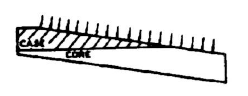 Fig 1 Taper Grind |
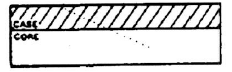 Fig. 2 Cross Section |
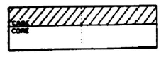 Fig. 3 Alternate Cross Section |
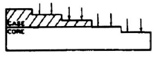 Fig 4 Step Grind |
Hardness Traverse Procedure - Cut specimens perpendicular to hardened surface at critical location being careful to avoid any cutting or grinding practice which would affect the original hardness.
Grind and polish specimen. Surface finish of the area to be traversed shall be polished finely enough so the hardness impressions are unaffected—that is, the lighter the indentor load, the finer the polish necessary.
The procedure illustrated by Figure 2 is recommended for the measurement of light and medium cases. The alternate procedure illustrated in Figure 3 is recommended for medium and heavier cases.
The hardness traverse should be started far enough below the surface to ensure proper support from the metal between the center of the impression and the surface. Subsequent impressions are spaced far enough apart so as not to distort hardness values. The distance from the surface of the case to the center of the impression is measured on a calibrated optical instrument, micrometer stage, or other suitable means.
Taper Grind Procedure - This procedure, illustrated by Figure 1, is recommended for measurement of light and medium cases.
A shallow taper is ground through the case, and hardness measurements are made along the surface thus prepared. The angle is chosen so that readings, spaced equal distances apart, will represent the hardness at the desired increments below the surface of the case.
Unless special anvils are used, a parallel section should be prepared so that readings are taken at right angles to the surface. Care should be exercised in grinding to prevent tempering or rehardening.
Step Grind Procedure - This procedure illustrated by Figure 4 is recommended for measurement of medium and heavy cases.
It is essentially the same as the taper grind section method with the exception that hardness readings are made on steps which are known distances below the surface.
A variation in this procedure is the step grind method where two predetermined depths are ground to insure that the effective case depth is within specified limits.
Visual Methods
This method employs any visual procedure with or without the aid of magnification for reading the depth of case produced by any of the various processes. Samples may be prepared by combinations of fracturing, cutting, grinding, and polishing methods. Etching with a suitable reagent is normally required to produce a contrast between the case and core. Nital (concentrated nitric acid in alcohol) of various strengths is frequently used for this purpose.
Macroscopic - Magnification methods for determination of case depth measurement are recommended for routine process control, primarily because of the short time required for determinations, and the minimum of specialized equipment and trained personnel needed. They have the added advantage of being applicable to the measurement of all types of cases. However, the accuracy can be improved by correlation with other methods more in keeping with engineering specifications for the parts being processed. These methods are applied normally to hardened specimens, and while a variety of etchants may be employed with equal success, the following procedures are typical and widely used.
Fracture - Prepare product or sample by fracturing. Examine at a magnification not to exceed 20 diameters with no further preparation.
Fracture and Wet - Water quench product or samples directly from the carburizing temperature. Fracture and etch in 20% nitric acid in water for a time established to develop maximum contrast. Rinse in water and read while wet.
Fracture or Cut and Rough Grind - Prepare specimen by either fracturing, or cutting and rough grinding. Etch in 10% nital for a period of time established to provide a sharp line of demarcation between case and core. Examine at magnification not to exceed 20 diameters (Brinell glass) and read all the darkened area for approximate total case depth.
Fracture or Cut and Polish or Grind - Prepare specimen by fracturing or cutting. Polish or grind through No. 000 or finer metallographic emery paper or both. Etch in 5% nital for approximately 1 min. Rinse in two clean alcohol or water rinses. Examine at magnification not to exceed 20 diameters (Brinell glass) and read all of the darkened zone. After correlation, effective case depth can be determined by reading from external surface of specimen to a selected line of the darkened zone.
Microscopic - Microscopic methods are generally for laboratory determination and require a complete metallographic polish and an etch suitable for the material and the process. The examination is made most commonly at 100 diameters.
Carburized Cases - The microscopic method may be used for laboratory determinations of total case and effective case depths in the hardened condition. When the specimen is annealed properly, the total case depth and the depth of the various zones—hypereutectoid, eutectoid, and hypoeutectoid - also can be determined quite precisely.
a. Hardened Condition
1. Fracture or cut specimen at right angles to the surface.
2. Prepare specimen for microscope and etch in 2 to 5% nital (concentrated nitric acid in alcohol).
3. For effective case depth, read from surface to metallographic structures which have been shown to be equivalent to 50 HRC.
4. For total case depth, read to the line of demarcation between the case and core. In alloy steels quenched from a high temperature, the line of demarcation is not sharp. Read all the darkened zone that indicates a difference in carbon from the uniform core structure.
b. Annealed Condition
1. For specimens previously hardened or not cooled under controlled conditions.
2. The specimen to be annealed may be protected by copper plate or any suitable means for preventing loss of carbon.
3. Pack in a small, thin-wall container with a suitable material such as charcoal.
4. Place container in furnace at 40 to 80 °C (75 to 150 °F) aboye the upper critical temperature (Ac3) for the core. (Generally an annealing temperature of 870 to 925 °C (1600 to 1700 °F) is satisfactory.)
5. Leave in furnace long enough for specimen to reach furnace temperature, but not for an excessive time at temperature, as carbon diffusion will increase total case depth.
c. Cooling Rates
1. Carbon Steels—A satisfactory cooling rate is obtained by cooling the container in mica, lime, or other insulating material at a rate which will reduce the temperature to 430 °C (800 °F) in 2-1/2 to 3 h. Cool as desired below 430 °C (800 °F).
2. Alloy Steels—Slower cooling rates or isothermal transformations are required. If martensite is retained in the structure, better contrast after etching may be obtained by tempering the specimens at 540 to 600 °C (1000 to 1100 °F). Cool as desired after tempering.
3. Section, prepare, and etch specimen as desired under 6.3.1, (a) Hardened Condition. Etching time is usually longer.
4. For total case depth measurement, read the depth of carbon enrichment.
5. For specimens cooled slowly after carburizing. If the production carburizing cycle provides the proper cooling rate, or the cooling rate is otherwise controlled as described for the annealed condition, specimens may be prepared and examined without reheating after carburizing. This is often possible when the parts are cooled in solid compound when the boxes are not too small.
Carbonitrided Cases - Carbonitrided cases are measured for total case depth in the hardened condition. High quenching temperatures, high alloy content of the steel, and high carbon content of the core decrease the accuracy of readings obtained by this method.
Cyanided Cases - Cyanided cases are thin, and only the microscopic method is recommended for accurate case depth measurements. The usual cyanide case contains a light etching layer followed by a totally martensitic constituent, which in turn is followed by martensite with increasing networks of other constituents, depending on the type of steel which has been cyanided. Cyanided cases are read in the hardened condition only and results reported as total case depth.
a. Section, prepare, and etch specimen,
b. Read to the line of demarcation between the case and core.
c. (When a sharp line of demarcation does not exist, the use of a hardness test such as described under Mechanical Methods is recommended.)
Nitrided Cases - The microscopic method is used chiefly in those situations where the available sample cannot readily be prepared for the more desirable hardness traverse method. It may be difficult to read the case depth because the nitride network gradually diminishes.
a. Section and prepare the specimen as described in Carburized Cases, - Hardened Condition.
b. Etch in 10% nital.
c. Read all darkened zone for total case depth.
Flame or Induction Hardened Cases - Since no chemical change occurs in flame or induction hardening, readings must be made in the hardened or hardened and tempered condition only. A procedure for reading effective case depth may be established by correlating microstructures with a hardness traverse method. A minimum hardness of 50 HRC is used commonly but some other point may be selected or required, for example, in lower carbon steels that do not reach 50 HRC when fully hardened. See Table 1. The microstructure at the selected location will differ depending on steel composition, prior treatment (annealed, heat treated, or other treatments) and on the hardness level chosen.
a. Section, prepare, and etch specimen, Hardened Condition.
b. For total case depth, read the entire zone containing structures hardened by the process.
c. For effective case depth, read to selected microstructure correlated with specified hardness.
References:
- SAE International
- The Engineering Society for Advancing Mobility Land Sea and Space
- SAE-J423, "Case Depth, Methods of Measuring"
Contribution by:
Unithrem Engineering
Mumbai, Maharashtra India
Link to this Webpage:
© Copyright 2000 -
2024, by Engineers Edge, LLC
www.engineersedge.com
All rights reserved
Disclaimer |
Feedback
Advertising
| Contact