Louvers Industrial / HVAC Review and Design Considerations
Manufacturing Knowledge Menu
Sheet Metal Knowledge Menu
Louvers HVAC / Industrial Review
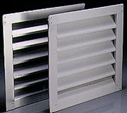
Louvers are very similar to dampers, except that the slats or vanes are manufactured at a fixed non-adjustable angle. Louvers are normally installed into a wall or other location to provide positive ventilation for a room or enclosed area.
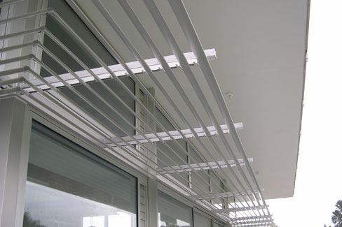
Louvers are available in all shapes, sizes and flow capabilities. Typically, louvers are made from sheet metal. Materials typically used are aluminum,or galvanized steel.
Background: A louver (American English) or louvre (British English), a derivative of the French word "l'ouvert" or "the open one") is a blind, window cover, or shutter with horizontal or vertical slats. The slats are designed at an angle that allows air to circulate\ within the room but not allow rain or direct sunshine. The angle of the slats are often adjustable or at a fixed angle.
Louver Design considerations:
Louvers are a basic and simple part of many HVAC systems and buildings, but they are often overlooked or not given the proper amount of design time and consideration. The purpose of this paper is to describe the proper way to select louvers, as well as point out application issues and common louver features and accessories. It is written for the beginner to the advanced reader in mind. To prevent the paper from being too long, some topics are only briefly mentioned. Additional conversations, details and supporting documents may be necessary to address specific applications.
- Determine the air flow, direction of air flow and maximum air pressure drop.
- On the Airflow Resistance chart, start at the selected static pressure and draw a horizontal line across, until it intersects either the intake line or the exhaust line. At the intersection point, draw a line straight down to the free area velocity line.
- Check the Water Penetration Chart to make sure the recently determined free area velocity is less than the beginning point of water penetration velocity.
- Calculate the free area required on the louver by taking the air flow amount and divide it by the recently determined free area velocity.
- Go to the Free Area Chart and select a louver that has a free area equal to or greater than the value found in item # 4.
- As a minimum, your louver schedule should include: manufacturer's name, louver model number, width, height, depth, free area, air flow amount, direction of air flow, static pressure drop and free area velocity.
Airflow = 8,500 ft3 / min, intake
Max PDs = 0.15" w.c.
Therefore, free area velocity = 1,000 fpm
8.500 cfm / 1,000 fpm = 8.5 ft2 min req'd free area
Link to this Webpage:
© Copyright 2000 -
2024, by Engineers Edge, LLC
www.engineersedge.com
All rights reserved
Disclaimer |
Feedback
Advertising
| Contact